Stable deduster equipment

A dust collector, stable technology, applied in the parts of the connection device, connection device connection/disconnection, electrical components, etc., can solve problems such as unstable power supply connection, exposure of the first power transmission hole, power failure of the dust collector, etc. To achieve the effect of safe and reliable operation of the device, stable power supply, and reduction of electric shock accidents

Inactive Publication Date: 2018-05-29
广州天品科技有限公司
View PDF1 Cites 5 Cited by
  • Summary
  • Abstract
  • Description
  • Claims
  • Application Information

AI Technical Summary

Problems solved by technology

[0002] At present, the plug-in and power-on of the dust collector is through directly passing the plug-in arm connected to it into the first power-transmitting hole. In the future, the plug arm can still be pulled out. When the kick accidentally hits the wire connected between the plug arm and the dust collector, the plug arm will be separated from the first power transmission hole, resulting in a sudden power failure of the dust collector. Therefore, the existing plug-in method has the risk of unstable power supply connection. In addition, when the dust collector is not in use, the plug arm is often pulled out from the first power transmission hole, and the first power transmission hole is always in a power-on state. This will cause the exposure of the first power transmission hole, therefore, there is a greater potential safety hazard

Method used


Image

  • Stable deduster equipment
  • Stable deduster equipment
  • Stable deduster equipment

Examples


Embodiment Construction

[0021] The preferred embodiments of the present invention will be described in detail below with reference to the accompanying drawings, so that the advantages and features of the present invention can be more easily understood by those skilled in the art, and the protection scope of the present invention can be more clearly defined.

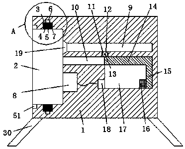
[0022] see Figure 1-6 A stable precipitator device shown in the figure includes a power transmission frame 1 and a power lead. , the first engaging groove 9 and the second engaging groove 10 are arranged oppositely, and the left ends of the first engaging groove 9 and the second engaging groove 10 are both communicated with the insertion slot 2, and the second engaging groove 10 is in communication with the insertion slot 2. The toothed slot 10 is in communication with the chute 17 , the right end of the insertion slot 2 is provided with a first power transmission hole 8 , and the left end of the lower part of the chute 17 is provided with a se...


PUM


Abstract

The invention discloses stable deduster equipment. The stable deduster equipment includes a power delivery frame and a power introducing member, wherein the power delivery frame includes an insertionconnection groove, a first mesh groove, a second mesh groove and a slide groove; the first mesh groove and the second mesh groove are arranged in an opposite manner, and both the left ends of the first mesh groove and the second mesh groove are communicated with the insertion connection groove; the second mesh groove is communicated with the slide groove; a first power delivery hole is formed in the right end portion of the insertion connection groove; a second power delivery hole is formed in the left end portion of the lower part of the slide groove; a gear hole is formed at the center of the first mesh groove and the second mesh groove, and is communicated between the first mesh groove and the second mesh groove; and a mesh gear is arranged in the gear hole through a rotation stick in arotary manner. The stable deduster equipment has the advantages of being reasonable in design, being simple in structure, being stable in power supply, reducing occurrence of electric shock accidentsin the present life, effectively guarantee life safety of people, reducing the production cost as coordinated connection between the insertion arm and the first power delivery hole and electrification of the first power delivery hole occur at the same time, automatically implementing locking and unlocking of the insertion connection member through control of a driving machine, being simple and convenient for operation, and being suitable for promotion and application.

Description

technical field [0001] The invention relates to the field of dust collectors, in particular to a stable dust collector equipment. Background technique [0002] At present, the plug-in and power-on of the dust collector is by directly passing the plug-in arm connected to it into the first power transmission hole. Although this plug-in method is simple to operate, the plug-in arm penetrates into the first power transmission hole In the future, the insert arm can still be pulled out. When it accidentally kicks and hits the wire connected between the insert arm and the precipitator, it will cause the insert arm to separate from the first power transmission hole, resulting in a sudden power failure of the precipitator. Therefore, the existing plug-in method has the risk of unstable power supply connection. In addition, when the precipitator is not in use, the plug-in arm is often pulled out from the first power transmission hole, and the first power transmission hole is always in...

Claims


Application Information

Patent Timeline
Patent Type & Authority Applications(China)
IPC IPC(8): H01R13/629H01R13/639H01R13/642H01R43/26
CPCH01R13/629H01R13/639H01R13/642H01R43/26
Inventor 汪任斌
Owner 广州天品科技有限公司
Why Eureka
Try Eureka