
A kind of l-shaped nozzle mold

A nozzle and mold technology, which is applied in the field of L-shaped nozzle molds, can solve the problems of small travel space, inability to design and control the tensile deformation and tearing of bellows, and achieve the effect of improving production efficiency.

Active Publication Date: 2020-04-10
安徽宁国中鼎模具制造有限公司
View PDF5 Cites 0 Cited by
  • Summary
  • Abstract
  • Description
  • Claims
  • Application Information

AI Technical Summary

Problems solved by technology

Three rows in different directions are formed, so that under the condition of a certain tonnage of the injection molding machine, the mold can only be designed with 1 out of 1 or 1 out of 2, and the L-shaped bellows of this design are in the mold opening direction of the upper and lower molds. , the row space is small, and the structure that controls the deformation and tearing of the bellows cannot be designed under the premise that the mold strength must be satisfied

Method used


Image

  • A kind of l-shaped nozzle mold
  • A kind of l-shaped nozzle mold
  • A kind of l-shaped nozzle mold

Examples


Embodiment Construction

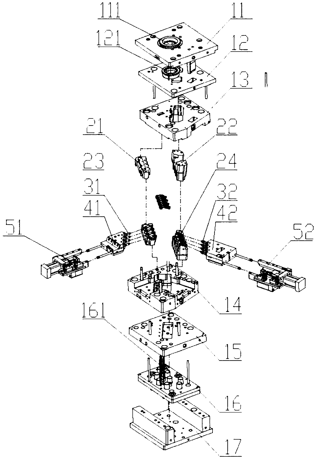
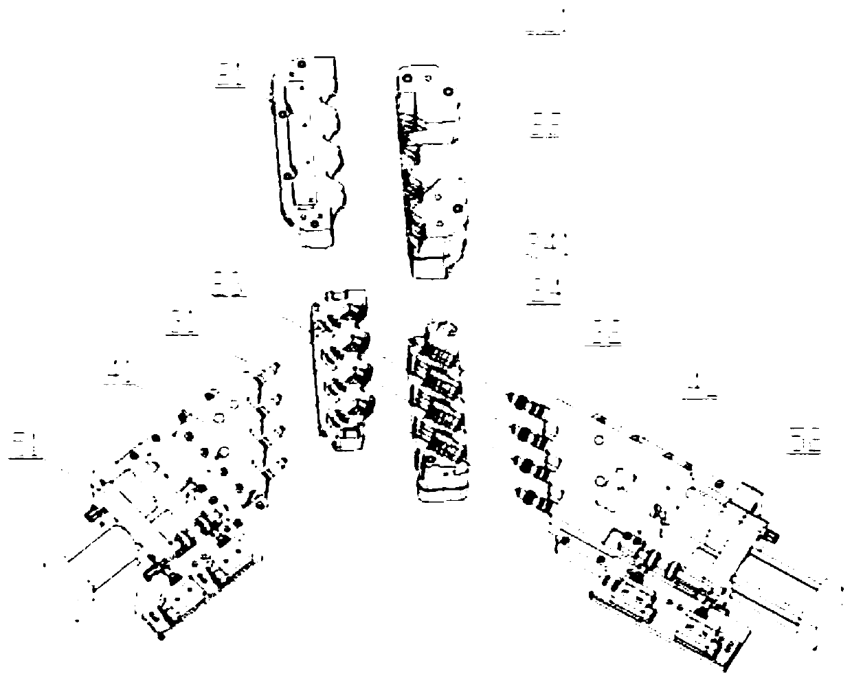
[0030] refer to Figure 1-3 , a kind of L-type nozzle mold that the present invention proposes, comprises; Panel 11, nozzle push plate 12, front template 13, push plate 14, rear template 15, thimble panel 16, square iron, bottom plate 17, inner mold 2, mold Core 3, slider 4, cylinder 5;

[0031] The panel 11 is provided with a main channel 111, and the nozzle push plate 12 is provided with a gate 121. The panel 11, the nozzle push plate 12 and the front formwork 13 are sequentially abutted against each other and installed and connected. The panel 11, the nozzle push plate 12 and the front formwork 13 can move along the direction of the gate 121; the thimble panel 16 and two square irons are fixed on one side of the bottom plate 17, and the side of the thimble panel 16 away from the bottom plate 17 is provided with a push rod 161, and one end of the push rod 161 is inserted in the inner mold 2 and It can move axially along the ejector rod 161, the rear template 15 is fixed on ...


PUM


Abstract

The invention discloses an L-shaped pipe nozzle die. The L-shaped pipe nozzle die comprises a panel, a water gap push plate, a front die plate, a push plate, a rear die plate, an inner die, die cores,sliding blocks and oil cylinders. The inner die is arranged between the front die plate and the push plate. The die cores stretch into a cavity from the two sides of the L-shaped cavity and abut against with each other, and the sliding blocks are fixedly connected with one ends of the die cores. The oil cylinders drive the sliding blocks to move, and then the die cores are driven to move in the cavity. The inner die is provided with a plurality of cavities, a plurality of products can be produced through one-time die opening in the production process, and the production efficiency is improved. Through control over the inner die opening sequence and the sliding block core pulling sequence in the die opening process, the situation that an L-shaped pipe nozzle is pulled by the die cores to walk along walking positions in the core pulling process is avoided, it is guaranteed that the corrugated position is not pulled or torn apart, and the situation that due to TPV flexible glue walking position bonding, products cannot be automatically demoulded is prevented.

Description

technical field [0001] The invention relates to the field of mold technology, in particular to an L-shaped nozzle mold Background technique [0002] Injection molding products in the automotive industry account for a large proportion. In order to ensure the normal operation of the air-conditioning system, the drain pipe assembly is particularly important. The L-shaped nozzle is the primary part of the drain assembly. For the new mold structure of the nozzle, one-mold multi-cavity product is an effective means to improve production efficiency. The traditional design is to stand up the product. In addition to the upper and lower molds, the product needs three rows to be formed together. Three rows in different directions are formed, so that under the condition of a certain tonnage of the injection molding machine, the mold can only be designed with 1 out of 1 or 1 out of 2, and the L-shaped bellows of this design are in the mold opening direction of the upper and lower molds. ...

Claims


Application Information

Patent Timeline
Patent Type & Authority Patents(China)
IPC IPC(8): B29C45/26B29C45/32B29C45/34B29C45/40B29C33/76B29C45/73B29L23/00
CPCB29C33/76B29C45/2612B29C45/263B29C45/32B29C45/332B29C45/34B29C45/401B29C45/7312B29C2045/2651B29L2023/004
Inventor 陈增宝韩双能任诚芬汪海滨宦昌虎
Owner 安徽宁国中鼎模具制造有限公司
Learn More