Intelligent lock control device, method and equipment
A smart lock and lock control technology, applied in building locks, lock applications, electric matching locks, etc., can solve the problem of inconvenient unlocking, achieve the effect of simplifying the unlocking process, low cost, and improving convenience
- Summary
- Abstract
- Description
- Claims
- Application Information
AI Technical Summary
Problems solved by technology
Method used
Image


Examples
Embodiment 1
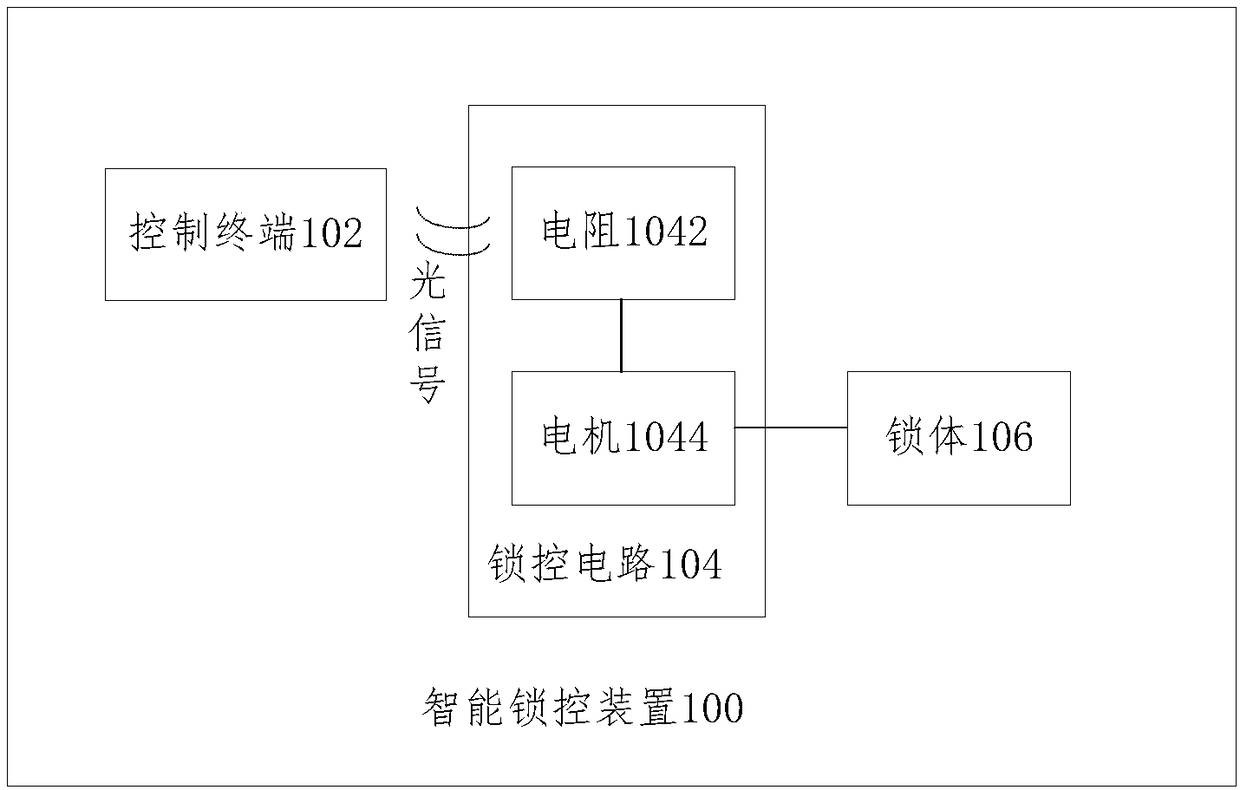
[0030] figure 1 An intelligent lock control device according to an embodiment of the present invention is shown.
[0031] Such as figure 1 As shown, the present invention proposes an intelligent lock control device 100, including: a control terminal 102 for receiving unlock information and sending an unlock signal; a lock control circuit 104 including a resistor 1042 and a motor 1044, and the resistor 1042 and the motor 1044 in series, wherein the resistor 1042 turns on the lock control circuit 104 after receiving the unlock signal, and the motor 1044 works; the lock body 106 is connected to the motor 1044, and the motor 1044 controls the opening and closing state .
[0032] Wherein, the resistor 1042 is a photosensitive resistor, and the unlocking signal is a light signal, wherein the display screen or the flash light of the control terminal 102 is set adjacent to the resistor 1042 to provide the light signal for the resistor 1042, wherein , the control terminal 102 and th...
Embodiment 2
[0038] figure 2 Shown is an intelligent lock control device according to another embodiment of the present invention.
[0039] Such as figure 2 shown, with figure 1 The difference between the embodiments is that the resistor 1046 is an ordinary resistor, and the control terminal 102 is connected to the resistor 1046 through a wire, and the control terminal 10 receives an incoming call or notification, and is operated on-site or remotely. A current pulse signal is generated, that is, an unlock signal, and the current pulse signal flows to the motor 1044 through the resistor 1046, so that the motor 1044 is instantly turned on, and the lock body 106 is driven to open.
[0040] In simple terms, the control terminal 102 is connected to the resistor 1046, and the unlock signal is sent along with the current, and the current passes through the resistor 1046 to the motor 1044 to make the motor 1044 work.
Embodiment 3
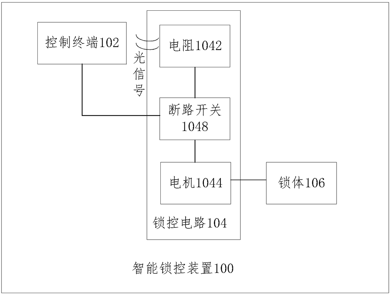
[0042] image 3 Shown is an intelligent lock control device according to another embodiment of the present invention.
[0043] Such as image 3 As shown, the control terminal 102 is also used to receive disconnection information and send a disconnection signal; the lock control circuit 104 also includes: a disconnection switch 1048 connected to the control terminal 102 and connected in series with the resistor 1042 for receiving the disconnection signal. After the above break signal is disconnected.
[0044]Among them, the disconnection information received by the control terminal 102 can be remote information, such as instruction information sent to a specified application program, etc., or user operation information for real-time operation by the user. information.
[0045] The disconnect switch 1048 is used to control the on-off of the lock control circuit 104, and when the unlock control is not required, the lock control circuit 104 can be disconnected to reduce power c...
PUM
 Abstract
Description
Claims
Application Information
 - Generate Ideas
- Intellectual Property
- Life Sciences
- Materials
- Tech Scout
- Unparalleled Data Quality
- Higher Quality Content
- 60% Fewer Hallucinations
Browse by: Latest US Patents, China's latest patents, Technical Efficacy Thesaurus, Application Domain, Technology Topic, Popular Technical Reports.
© 2025 PatSnap. All rights reserved.Legal|Privacy policy|Modern Slavery Act Transparency Statement|Sitemap|About US| Contact US: help@patsnap.com