Check patentability & draft patents in minutes with Patsnap Eureka AI!

Drive for sheet-fed rotary printing presses

A technology of drive and printing mechanism, applied in the direction of rotary printing machine, printing machine, general parts of printing machinery, etc., can solve the problem that the driving motor coupling has not been further described

Active Publication Date: 2018-06-08
MAN ROLAND MASCHINEN AG
View PDF16 Cites 1 Cited by
  • Summary
  • Abstract
  • Description
  • Claims
  • Application Information

AI Technical Summary

Problems solved by technology

[0012] Furthermore, drive systems are known with drive motors that drive directly into the continuous gear train between the rollers guiding the paper, wherein the coupling of the drive motors is not further described

Method used


Image

  • Drive for sheet-fed rotary printing presses
  • Drive for sheet-fed rotary printing presses
  • Drive for sheet-fed rotary printing presses

Examples


Embodiment Construction

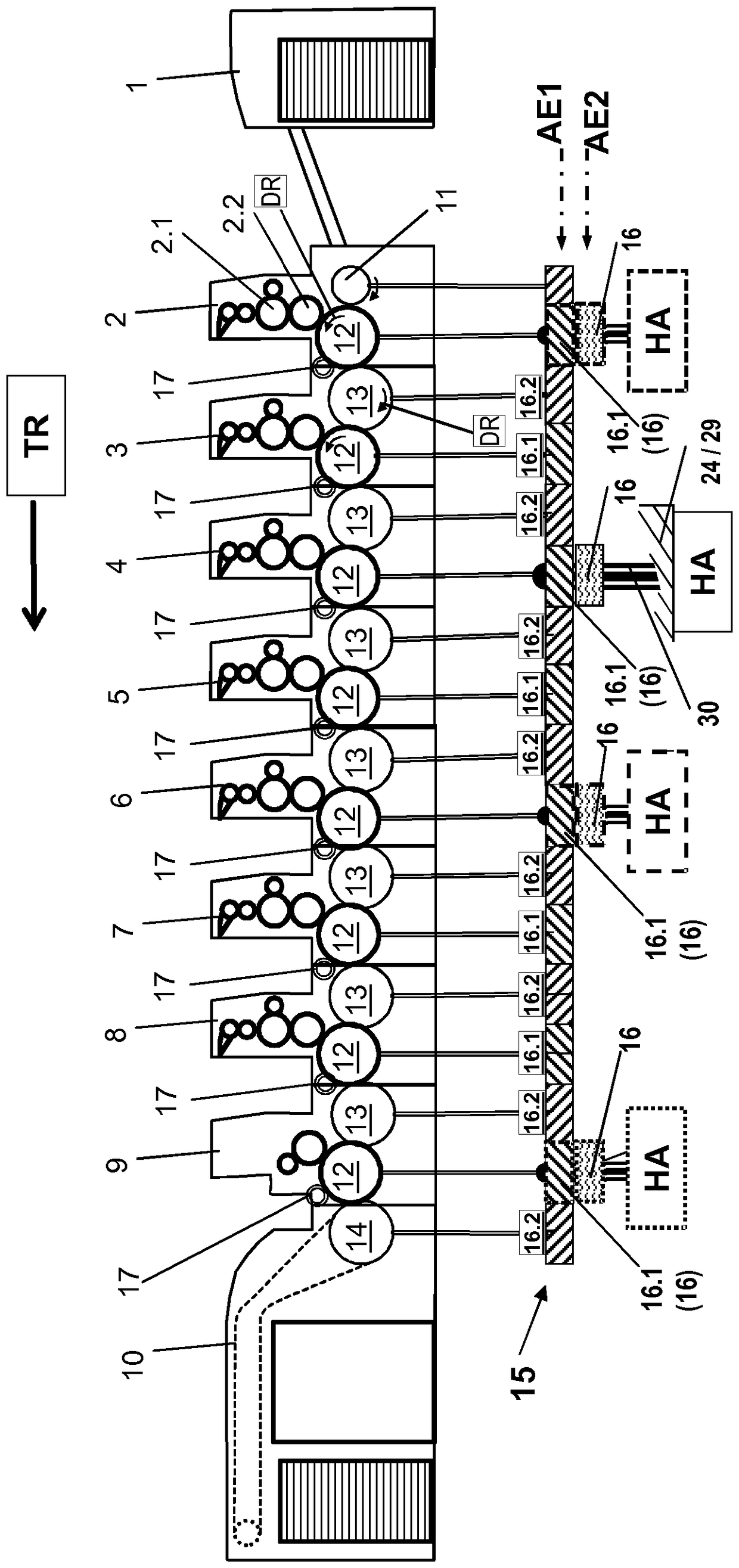
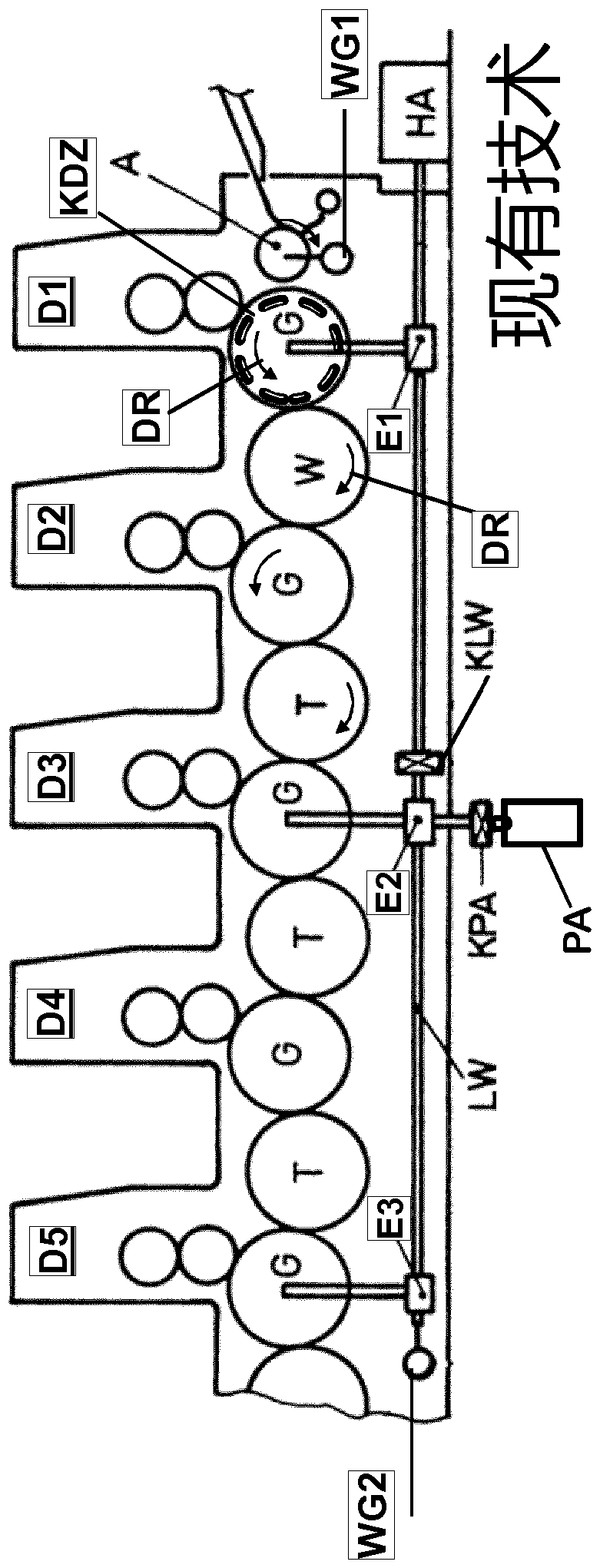
[0059] exist figure 1 The paper offset printing machine on which the invention is based is shown in , the drive arrangement of which is in figure 2 , where five printing units D1 to D5 of an offset paper printing press are shown in side or top view with an impression cylinder G and a transfer or wraparound guide cylinder in between ( Umführtrommeln) T. The printing paper to be printed is fed via the feed reel A to the impression cylinder G of the first printing unit D1. This is followed by the deflection drum W which is upstream of the impression cylinder G of the second printing unit D2. During the changeover from front-side printing to front-side and reverse-side printing, the printing sheet is deflected after the printing unit D1 and fed via the deflection drum W to the impression cylinder G in the printing unit D2 .

[0060] The main drive motor HA is driven into the longitudinal axis LW, which is driven into the drive wheels of the impression cylinders G of the printi...


PUM


Abstract

A drive for a sheet-fed offset printing press having a feeder (1), one or more printing units (2 to 8), one or more varnishing modules (9) or other printing press units and a deliverer (10) is to operate more exactly. A back-pressure cylinder and a transfer drum (11, 13, 14) are provided in each printing unit (2 to 8) for sheet transport. All sheet-conducting cylinders and drums (11, 12, 13, 14) are connected to a continuous drive wheel train (15). Drive wheels (16, 16.1) are connected to the back-pressure cylinders (12). One or more drive printing units (33) are provided in the drive for transmitting the drive power from the main drive motor (HA) directly into the drive wheel train (15) of the sheet-fed offset printing press.

Description

technical field [0001] The invention relates to a drive for a rotary printing press for paper in a tandem configuration according to the preamble of patent claim 1 . Background technique [0002] Drives for rotary paper printing presses arranged in series are known, the individual printing units of which are coupled via closed gear trains (eg DE-AS2334177, US-PS2115975). [0003] It is also known to use a proprietary drive transmission at a closed gear train in each printing unit (eg DD-WP159862). A disadvantage of a closed gear train is that, due to vibrations, tolerances, etc., mutual influences of the printing units cannot be avoided. The different drive torques partly lead to a considerable load increase of the drive elements, which leads to premature wear of the drive and to a reduction in the print quality of the product. In the case of closed gear trains, solutions consumed in the front and back printing units are required for achieving phase shifting (eg DE-GM83194...

Claims


Application Information

Patent Timeline
IPC IPC(8): B41F13/004B41F13/008B41F13/016
CPCB41F13/0045B41F13/008B41F13/016B41P2213/91
Inventor J.舍尔齐希
Owner MAN ROLAND MASCHINEN AG
Features
  • R&D
  • Intellectual Property
  • Life Sciences
  • Materials
  • Tech Scout
  • Unparalleled Data Quality
  • Higher Quality Content
  • 60% Fewer Hallucinations
Learn More