
Cabinet fan control method and module

A technology of fan control and control module, applied in pump control, mechanical equipment, machine/engine, etc., can solve problems such as server performance reduction

Inactive Publication Date: 2020-01-31
MITAC COMP (SHUN DE) LTD +1
View PDF2 Cites 0 Cited by
  • Summary
  • Abstract
  • Description
  • Claims
  • Application Information

AI Technical Summary

Problems solved by technology

However, in this way, the performance of the server may be reduced

Method used


Image

  • Cabinet fan control method and module
  • Cabinet fan control method and module

Examples


Embodiment Construction

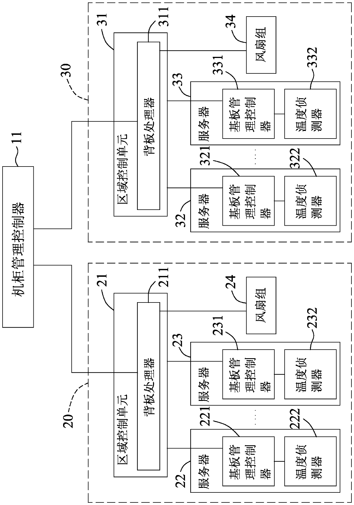
[0019] refer to figure 1 , an embodiment of the cabinet fan control module of the present invention is suitable for being arranged in a server cabinet (not shown in the figure), and the cabinet includes a plurality of fan groups respectively corresponding to a cooling area, and a plurality of fan groups respectively arranged in these fan groups Servers in the corresponding cooling zone.

[0020] Wherein, each fan group includes a plurality of fans, and the number of servers in the heat dissipation area corresponding to any fan group can be one, or two, three or more, for example figure 1 The servers 22, 23 arranged in the heat dissipation area 20, and the servers 32, 33 arranged in the heat dissipation area 30, and each server includes a baseboard management controller for monitoring the operation of the server, and a baseboard management controller for A temperature detector that detects and generates temperature data corresponding to the area where the server is located. T...


PUM


Abstract

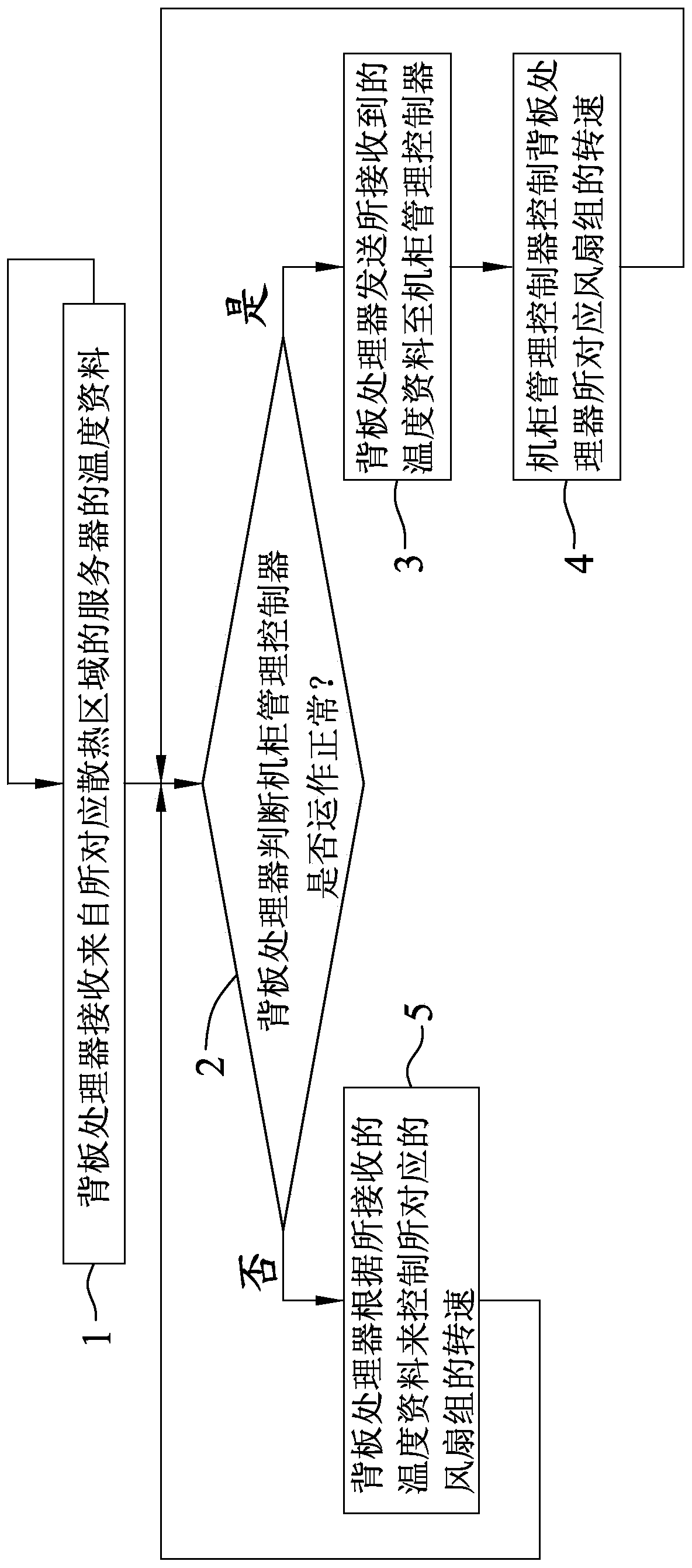
A machine cabinet fan control method is implemented through a machine cabinet fan control module. The module is suitable for controlling a plurality of fan sets each corresponding to a heat-dissipating area, and comprises a machine cabinet management controller and a plurality of area control units. The method comprises the steps that each area control unit receives a temperature datum from a corresponding connected server; each area control unit detects whether the machine cabinet management controller normally operates or not; as for each area control unit, if the detecting result is normaloperating, the rotating speed of the fan set corresponding to the area control unit is controlled by the machine cabinet management controller; and if the detecting result is abnormal operating, the area control unit controls the rotating speed of the corresponding fan set according to the received temperature datum, and thus two-stage-type fan control is achieved.

Description

technical field [0001] The present invention relates to a control method and module, in particular to a cabinet fan control method and module. Background technique [0002] Generally speaking, the server cabinet generates air flow through the operation of a plurality of fan groups arranged at the rear side, so as to reduce the temperature of the servers disposed in the heat dissipation area corresponding to each fan group. The rotation speed of these fan groups is controlled by a Rack Management Controller (RMC for short), and the Rack Management Controller will collect the temperature of heat sources (such as servers) in the cabinet or other heat dissipation requirements to determine the Wait for the speed of the fan group. [0003] However, when the rack management controller is damaged or is removed from the rack during maintenance, the fan groups will be in a state of no master control; for this situation, the existing processing methods generally have the following met...

Claims


Application Information

Patent Timeline
Patent Type & Authority Patents(China)
IPC IPC(8): F04D27/00G06F1/20
CPCF04D27/00F04D27/004F04D27/007G06F1/20
Inventor 王博玮
Owner MITAC COMP (SHUN DE) LTD
Learn More