
Heating furnace body and semiconductor device

A heating furnace and heating zone technology, which is applied in the field of heating furnace body and semiconductor equipment, can solve the problems of reduced production capacity, increased process cost, and poor uniformity of film thickness, so as to improve heating efficiency, shorten heating time, and improve process uniformity Effect

Active Publication Date: 2019-12-03
BEIJING NAURA MICROELECTRONICS EQUIP CO LTD
View PDF9 Cites 8 Cited by
  • Summary
  • Abstract
  • Description
  • Claims
  • Application Information

AI Technical Summary

Problems solved by technology

[0003] In practical applications, the graphite sheets in the graphite boat are placed vertically (placed along the axial direction of the tubular furnace body), and multiple graphite sheets are distributed at intervals along a diameter direction of the tubular furnace body, which makes the outermost The two graphite sheets closest to the furnace body have the highest heat absorption rate and the fastest temperature rise, while the middle graphite sheet has a low heat absorption rate due to the blockage of the outer graphite sheet. It is necessary to increase the heating power and prolong the heating time to make the middle The graphite flakes meet the temperature requirements, but increasing the heating power will increase the process cost, and prolonging the heating time will lead to a decrease in production capacity
In addition, due to the temperature difference between the graphite sheets, the thickness uniformity of the film layer is poor

Method used


Image

  • Heating furnace body and semiconductor device
  • Heating furnace body and semiconductor device
  • Heating furnace body and semiconductor device

Examples


Embodiment Construction

[0038] In order for those skilled in the art to better understand the technical solution of the present invention, the heating furnace body and semiconductor equipment provided by the present invention will be described in detail below with reference to the accompanying drawings.

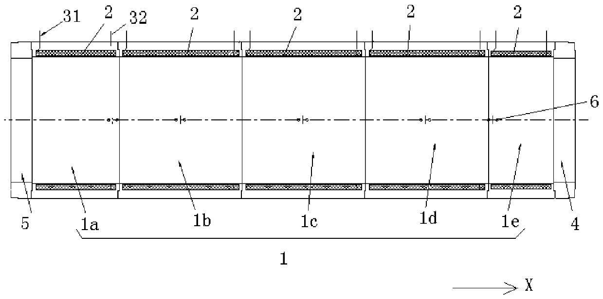
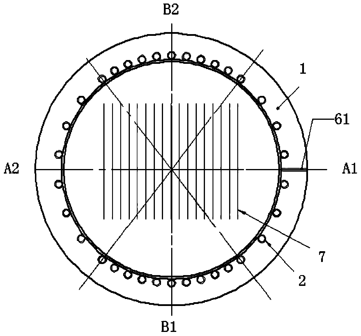
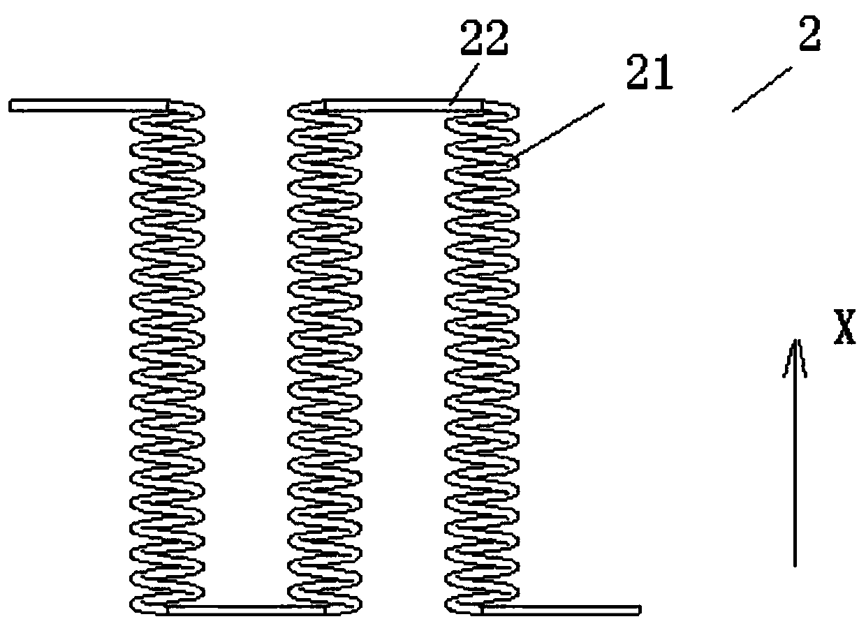
[0039] Please also refer to Figure 1 to Figure 6 , the heating furnace body provided by the embodiment of the present invention includes a plurality of annular heat insulating bodies 1 and a plurality of heating structures 2, wherein the annular insulating body 1 includes a plurality of annular split bodies, and along its axial direction (that is, figure 1 in the X direction) are sequentially connected to form a continuous ring, for example, figure 1 Five ring splits (1a-1e) are shown. The number of heating structures 2 is the same as that of the annular split bodies, and each heating structure 2 is arranged on the inner side of each annular split body in a one-to-one correspondence.

[0040] Opt...


PUM


Abstract

The invention provides a heating furnace body and semiconductor device. The heating furnace body comprises an annular heat preservation body; and heating structures which are independent of one another and are sequentially arranged on the inner side of the annular heat preservation body in the axial direction of the annular heat preservation body; moreover, at least one heating structure comprisesa plurality of heating subsections which are in one-to-one correspondence with a plurality of subareas divided in the circumferential direction of the annular heat preservation body, and heat radiated by at least two heating subsections at the same time is different. According to the heating furnace body provided by the invention, the heating efficiency can be improved, the heating time can be shortened and the process uniformity can be improved under the condition of the same or less heating power.

Description

technical field [0001] The invention relates to the technical field of semiconductors, in particular to a heating furnace body and semiconductor equipment. Background technique [0002] In the existing plasma enhanced chemical vapor deposition (Plasma Enhanced Chemical VaporDeposition, hereinafter referred to as PECVD) equipment, the reaction chamber usually adopts a tubular furnace body, and the furnace body temperature field is designed to be uniformly heated in the circumferential direction. The specific heating structure is to use resistance wire After being uniformly wound and shaped, wrap insulation cotton on the outside. During the operation of the process, the graphite boat first enters the tubular furnace body in a cold state, and then waits for the overall temperature of the tubular furnace body to return to the process temperature before starting the coating process. [0003] In practical applications, the graphite sheets in the graphite boat are placed verticall...

Claims


Application Information

Patent Timeline
Patent Type & Authority Applications(China)
IPC IPC(8): C23C16/50C23C16/52C23C16/46F27D11/02
CPCC23C16/50C23C16/52F27D11/02H01L21/67098H01L21/67103H01L21/67017Y02P70/50
Inventor 郝晓明郑建宇赵福平盛强
Owner BEIJING NAURA MICROELECTRONICS EQUIP CO LTD
Learn More