Al technical title is built by PatSnap Al team. It summarizes the technical point description of the patent document.
An automatic lifting and tilting technology, applied in the direction of lifting devices, lifting frames, etc., can solve the problems of inability to move, high risk, high degree of danger, etc., and achieve the effect of simple structure, high safety and convenient use
Inactive Publication Date: 2018-06-19
TAIZHOU KELUOMIDE MACHINERY EQUIMENT CO LTD
View PDF0 Cites 1 Cited by
Summary
Abstract
Description
Claims
Application Information
AI Technical Summary
This helps you quickly interpret patents by identifying the three key elements:
Problems solved by technology
Method used
Benefits of technology
Problems solved by technology
[0002] At present, with the improvement of people's living standards, the number of cars is increasing, and the number of scrapped cars is also increasing year by year. When maintaining a car, it is necessary to lift the chassis of the car to operate. Most of the lifting devices used now are The use of spring steel for lifting has a high degree of danger. If it is used improperly, it will cause irreversible damage to the staff below, and most of them are fixed on the ground and cannot be moved. It is inconvenient to use and highly dangerous. Therefore, a solution is needed. solve the above problems
Method used
Image
Click on the blue label to locate the original text in one second.
Reading with bidirectional positioning of images and text.
Examples
Embodiment Construction
[0011] The preferred embodiments of the present invention are given below in conjunction with the accompanying drawings to describe the technical solution of the present invention in detail.
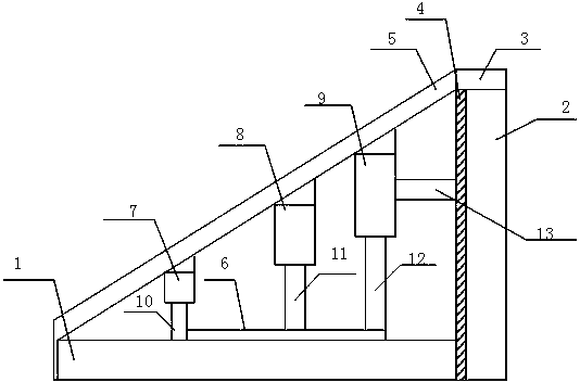
[0012] Such as figure 1 As shown, a tilting automatic lifting device includes a base 1, a bracket 2, a discharge port 3, a socket 4, an external panel 5, a connecting shaft 6, a first support rod 7, a second support rod 8, a third Support rod 9, the first hydraulic rod 10, the second hydraulic rod 11, the third hydraulic rod 12 and the cross bar 13, the support 2 is installed on the right side of the base 1, the discharge port 3 is installed on the top of the support 2, and the socket 4 is installed on the On the left side of the bracket 2, the outer panel 5 connects the base 1 and the discharge port 3, the first support rod 7, the second support rod 8 and the third support rod 9 are installed between the base 1 and the outer panel 5 in sequence, and the first hydraulic rod 10. The seco...
PUM
Abstract
The invention discloses an inclined automatic lifting device. The inclined automatic lifting device includes a base, a bracket, a discharge port, an embedded groove, an external panel, a connection shaft, a first support rod, a second support rod, a third support rod, a first hydraulic rod, a second hydraulic rod, a third hydraulic rod, and a cross bar. The first hydraulic rod, the second hydraulic rod, and the third hydraulic rod are installed below the first support rod, the second support rod, and the third support rod, the connection shaft is connected with the first hydraulic rod, the second hydraulic rod, and the third hydraulic rod, and the cross bar is connected with the support rods and the embedded groove. The inclined automatic lifting device utilizes the three support rods in cooperation with the hydraulic rods, so that shaking is not prone to occurring when a chassis is lifted and lowered, the three hydraulic rods share the force after the chassis is lifted, the safety ishigh, an inclined panel can quickly enable the lifting device to be clamped into the underneath of the chassis of a car, using is easy and the structure is simple, and the inclined automatic lifting device does not need to be fixed on the ground during using.
Description
technical field [0001] The invention relates to a lifting device, in particular to an inclined automatic lifting device. Background technique [0002] At present, with the improvement of people's living standards, the number of cars is increasing, and the number of scrapped cars is also increasing year by year. When maintaining a car, it is necessary to lift the chassis of the car to operate. Most of the lifting devices used now are The use of spring steel for lifting has a high degree of danger. If it is used improperly, it will cause irreversible damage to the staff below, and most of them are fixed on the ground and cannot be moved. It is inconvenient to use and highly dangerous. Therefore, a solution is needed. Solve the above problems. Contents of the invention [0003] The technical problem to be solved by the present invention is to provide an inclined automatic lifting device. [0004] The present invention solves the above technical problems through the followin...
Claims
Application Information
Patent Timeline
Application Date:The date an application was filed.
Publication Date:The date a patent or application was officially published.
First Publication Date:The earliest publication date of a patent with the same application number.
Issue Date:Publication date of the patent grant document.
PCT Entry Date:The Entry date of PCT National Phase.
Estimated Expiry Date:The statutory expiry date of a patent right according to the Patent Law, and it is the longest term of protection that the patent right can achieve without the termination of the patent right due to other reasons(Term extension factor has been taken into account ).
Invalid Date:Actual expiry date is based on effective date or publication date of legal transaction data of invalid patent.