Device for placing angle device in electric tool

A technology of electric tools and anglers, applied in auxiliary devices, measuring devices, manufacturing tools, etc., can solve the problems of limited workshop space, occupied space, damage, etc., and achieve the effect of convenient operation and easy access

Inactive Publication Date: 2013-09-04
JIANGSU JINFEIDA POWER TOOLS
View PDF0 Cites 0 Cited by
  • Summary
  • Abstract
  • Description
  • Claims
  • Application Information

AI Technical Summary

Problems solved by technology

Generally speaking, the angler is placed next to the power tool, and it is used when working, and it is put aside after the work. However, the space of the workshop is limited. It is easy to cause the loss or damage of the angler

Method used


Image

  • Device for placing angle device in electric tool
  • Device for placing angle device in electric tool
  • Device for placing angle device in electric tool

Examples


Embodiment Construction

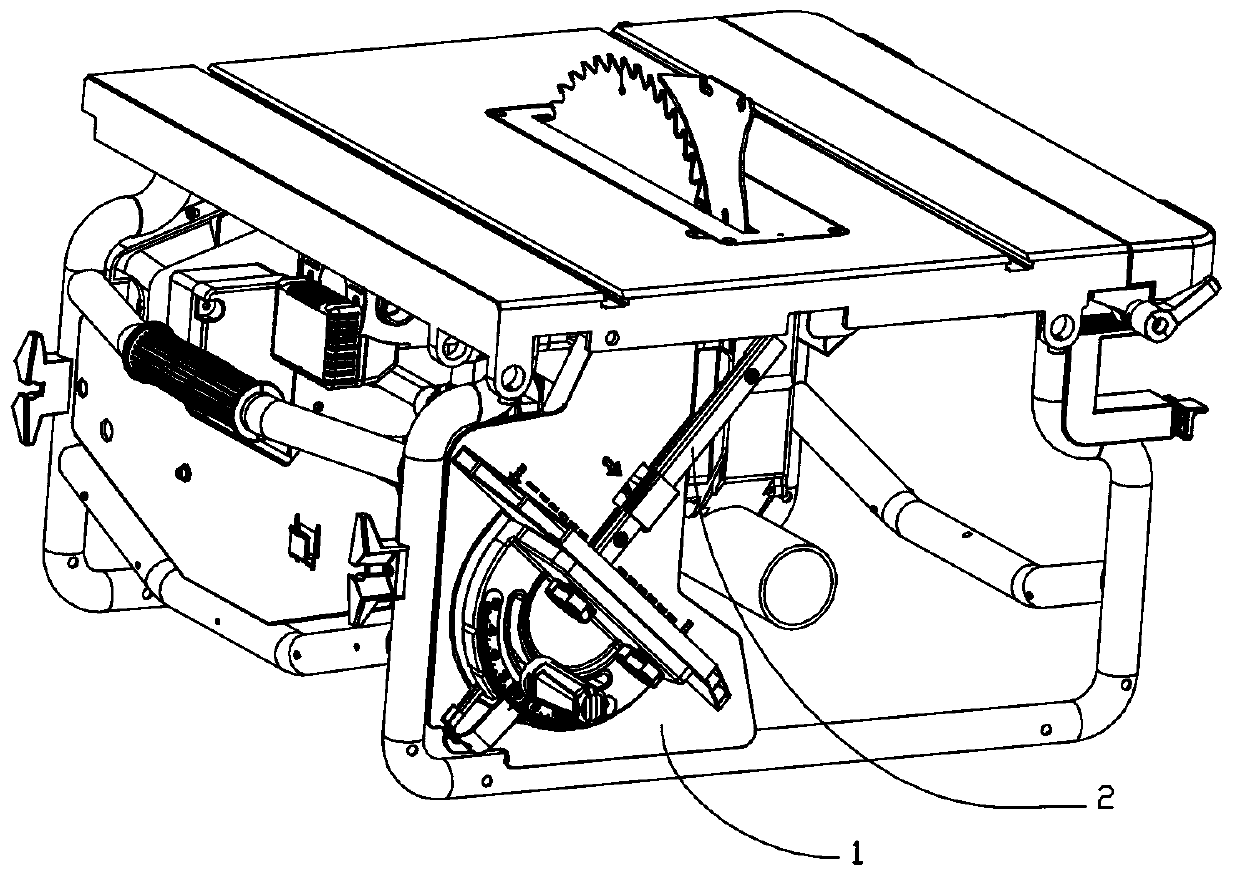
[0010] Such as figure 1 As shown, the device of the present invention is located on one side of the electric tool and does not occupy space.

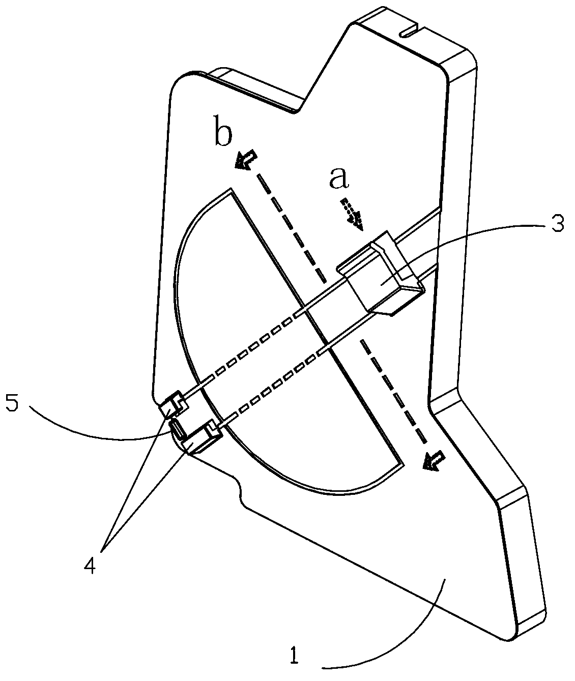
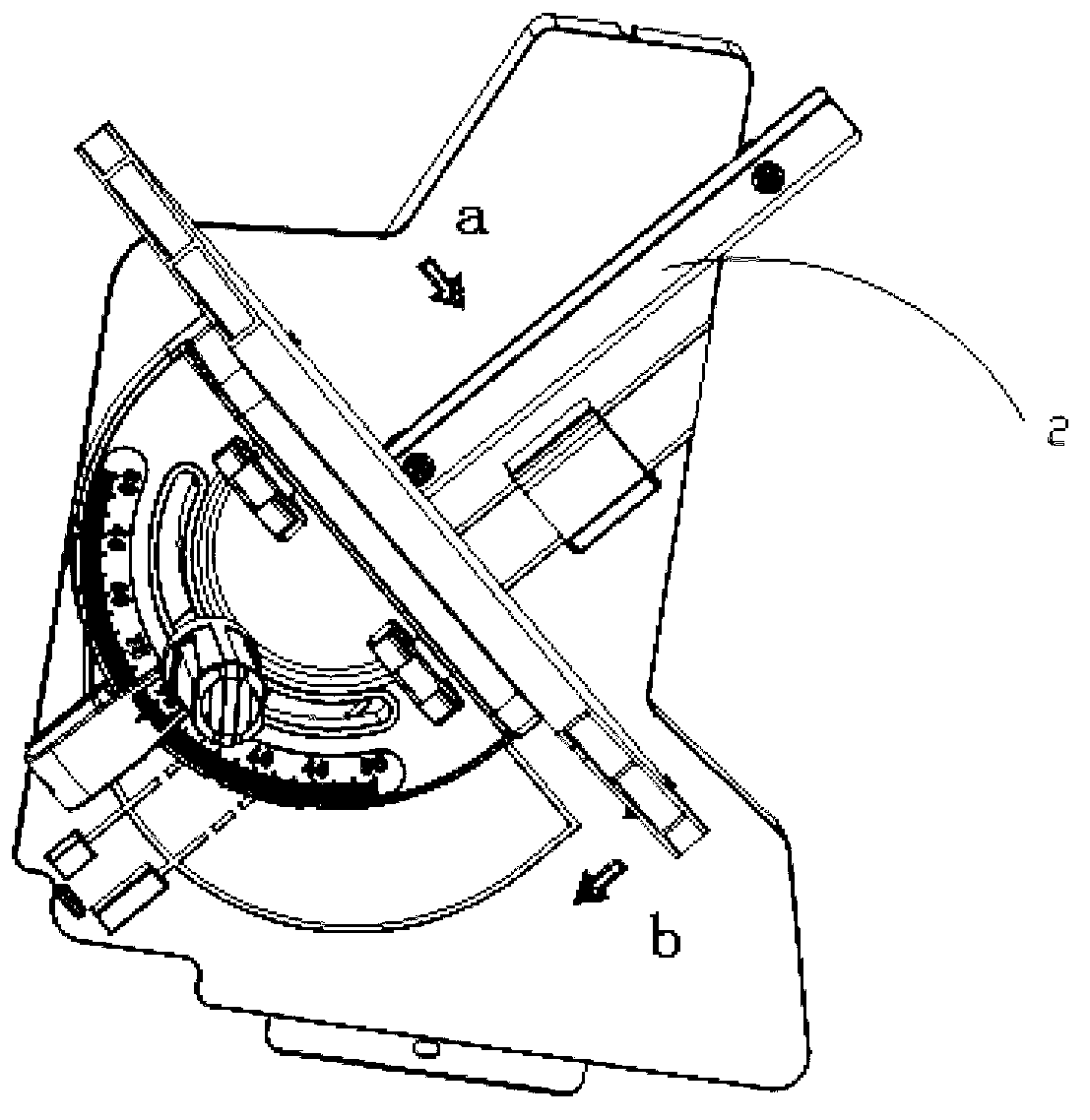
[0011] Such as figure 2 As shown, the polygonal shape of the panel 1 is to cooperate with other components in the electric tool, so that the device of the present invention can be installed on one side of the electric tool. The panel 1 is marked with two mutually perpendicular indicating directions a, indicating directions b and an angle-shaped pattern. The indication direction a points to the direction of the U-shaped notch of the first positioning press card 3; The slot is short, and one slot is long. The function of these two slots is that the guide rod 2 of the angler can be quickly inserted into the slot, accurately positioned, and convenient to take out, shortening the operation time. The cooperative use of the first positioning pressing card 3 and the second positioning pressing card 4 can ensure that the angler will not fall...


PUM


Abstract

The invention discloses a device for placing an angle device in an electric tool. One side of the electric tool is provided with a panel, and a positioning pressing clamp for clamping an angle device guiding bar is arranged on the panel. The device for placing the angle device in the electric tool has the advantages that the device for placing the angle device is arranged in the electric tool, the angle device can be conveniently taken and used, an extra space is not needed, meanwhile, the angle device can be rapidly clamped into and pulled out of the device, and therefore operation is convenient.

Description

technical field [0001] The invention relates to an electric tool, in particular to a device for placing an angler in the electric tool. Background technique [0002] When cutting and welding workpieces, anglers are often used to measure angles to ensure the accuracy of work. Generally speaking, the angler is placed next to the power tool, and it is used when working, and it is put aside after work, and the space of the workshop is limited. It is easy to cause the loss or damage of the angler. Contents of the invention [0003] Object of the invention: The object of the invention is to provide a device for placing an angler in an electric tool. [0004] Technical solution: A device for placing an angler in an electric tool according to the present invention, a panel is installed on one side of the electric tool, and the panel is provided with a positioning clamp for clamping the guide rod of the angler. [0005] Wherein, the positioning pressing card is a first positioni...

Claims


Application Information

Patent Timeline
Patent Type & Authority Applications(China)
IPC IPC(8): G01B21/22B23K37/00
Inventor 张庆奇朱金宝
Owner JIANGSU JINFEIDA POWER TOOLS
Why Eureka
Try Eureka