Scaffold with adjustable height

A technology of height adjustment and scaffolding, which is applied in the field of scaffolding, can solve problems such as the inability to quickly and conveniently adjust the height of the scaffolding, the inability to ensure the scaffolding, and the inability to further ensure the stability of the scaffolding, so as to reduce the possibility of overturning, reduce the occupied space, and improve The effect of stability

Inactive Publication Date: 2021-09-24
云南六洲建筑劳务有限公司
View PDF0 Cites 3 Cited by
  • Summary
  • Abstract
  • Description
  • Claims
  • Application Information

AI Technical Summary

Problems solved by technology

[0004] The purpose of the present invention is to provide a height-adjustable scaffold to solve the problem that the above-mentioned background technology cannot further ensure the stability of the scaffold during use, cannot adjust the height of the scaffold quickly and conveniently, and cannot ensure that the scaffold is convenient for transportation. , can also facilitate quick installation of the problem

Method used


Image

  • Scaffold with adjustable height
  • Scaffold with adjustable height
  • Scaffold with adjustable height

Examples


Embodiment 1

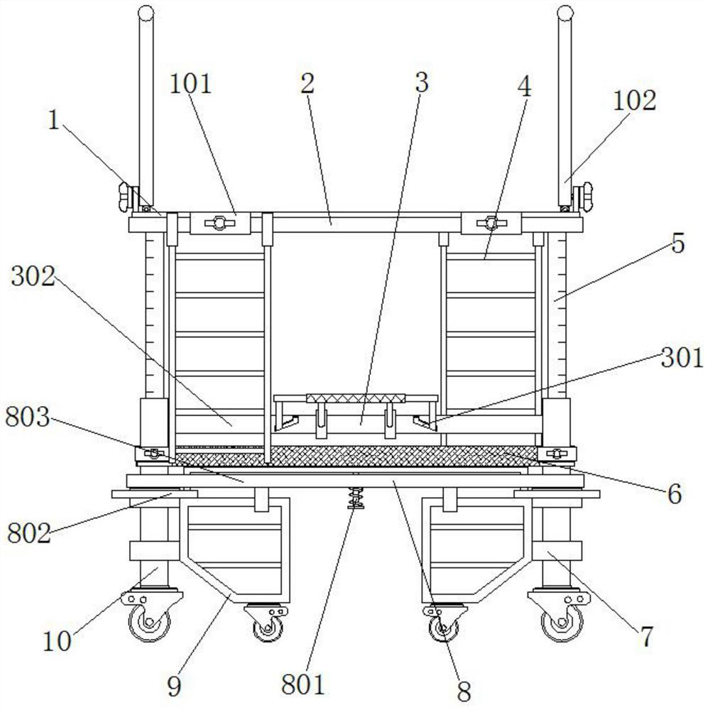
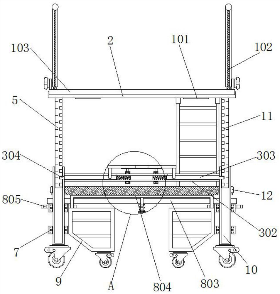
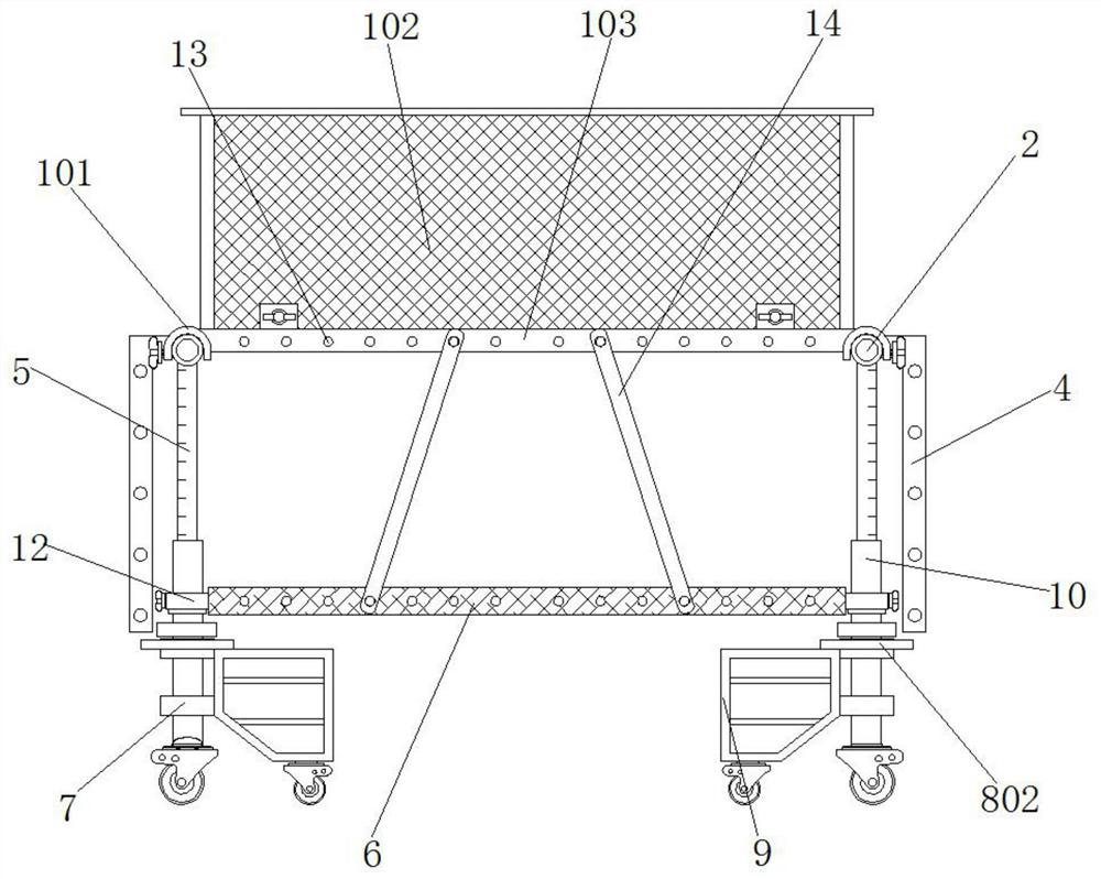
[0046] Example 1, such as Figure 1-9 As shown, when installing the scaffolding, the installer first erects the four sets of installation pipes 10, allows the installation pipes 10 and the universal wheels at the bottom of the support frame 9 to be placed on the ground, and then lifts the connecting plate 6 into the four sets of installation pipes 10 between, and through four sets of second steel pipe buckles 12, the connecting plate 6 is fixedly connected with the four sets of installation pipes 10, and then the auxiliary plate 807 is lifted up manually, so that the two ends of the bottom of the latch 304 leave the corresponding fixing hole 805, Unfix the position of the support frame 9, and rotate the support frame 9 to the outside of the scaffold as attached to the instruction manual. Figure 4 , and then loosen the auxiliary plate 807, so that the bottoms of the two ends of the U-shaped bar 804 snap into the corresponding fixing holes 805, so that the support frame 9 is li...

Embodiment 2

[0047] Example 2, such as Figure 1-9 As shown, when it is necessary to adjust the height of the entire scaffold, the four sets of connecting rods 14 are first removed from the corresponding limit protrusions 13, and then the operator supports the platform board 103 with both hands, and the two sets of hand pipes 308 are moved to the The inner side of the scaffold rotates, forcing the movable rod 303 to gradually move towards the middle position of the connecting pipe 302. After the latch 304 leaves the inside of the pin hole 11, the limiting hole 301 limits the L-shaped inserting rod 307, and at the same time the L-shaped inserting The rod 307 also extends into the inside of the handle pipe 308, the return spring 306 shortens and stores elastic potential energy, and then the installer can lift the construction frame assembly 1 upwards, and the four sets of lifting rods 5 also follow the direction of the installation pipe 10. The inside protrudes, and after the construction fr...


PUM


Abstract

The invention discloses a scaffold with adjustable height. The scaffold comprises four sets of mounting pipes, lifting rods are arranged in the mounting pipes, cross rods are jointly mounted at the tops of the two sets of lifting rods at the same end, pin holes are evenly formed in the outer sides of the lifting rods, a scaffold assembly is jointly arranged at the tops of the two sets of cross rods, and two groups of second bearings are symmetrically arranged at the bottoms of the outer sides of the four groups of mounting pipes. According to the scaffold with the adjustable height, through cooperative use of a lifting adjusting assembly, a lifting rod, a connecting plate, the pin holes and a second steel pipe buckle, an operator stands on the top of the connecting plate, two hands support the scaffold assembly upwards, a second operator manually pulls a hand pulling pipe, and after the operator manually lifts or lowers the scaffold assembly, the operator only needs to push the hand pulling pipe towards the outer side of the scaffold with feet, plug pins can be rapidly clamped into the corresponding pin holes, and therefore the height of the scaffold can be rapidly adjusted and fixed.

Description

technical field [0001] The invention relates to the technical field of scaffolding, in particular to a height-adjustable scaffolding. Background technique [0002] Assembled scaffolding is a variety of supports erected on the construction site for workers to operate and solve vertical and horizontal transportation. Assembled scaffolding is used on the construction site where the exterior wall, interior decoration or high floor height cannot be directly constructed. It is mainly for construction workers to work up and down. Or peripheral safety net maintenance and high-altitude installation components, etc., assembly scaffolding is usually made of bamboo, wood or steel pipes, etc., and now steel pipe assembly brackets are the most widely used. [0003] The current scaffolding for construction often requires other personnel to support the scaffolding during use, and the scaffolding itself will be very unstable when the user stands on it, which cannot further improve the stabil...

Claims


Application Information

Patent Timeline
Patent Type & Authority Applications(China)
IPC IPC(8): E04G1/22E04G1/15E04G1/24E04G5/02E04G5/00E04G5/08E04G5/14E04G7/28
CPCE04G1/22E04G1/15E04G1/24E04G5/02E04G5/001E04G5/08E04G5/14E04G7/28E04G2001/242E04G2005/148E04G2007/285
Inventor 不公告发明人
Owner 云南六洲建筑劳务有限公司
Why Eureka
Try Eureka