Oil level state detection method and device of transformer

A state detection and transformer technology, applied in measuring devices, lubrication indicating devices, instruments, etc., can solve problems such as hidden safety hazards, inability to grasp oil level status in real time, transformers unable to operate safely, etc., to ensure safe and stable operation and accurate monitoring results. Reliable, free of human resource consumption effect

Active Publication Date: 2018-06-19
SHENZHEN POWER SUPPLY BUREAU +1
View PDF6 Cites 4 Cited by
  • Summary
  • Abstract
  • Description
  • Claims
  • Application Information

AI Technical Summary

Problems solved by technology

[0002] The insulating oil inside the transformer has a much higher dielectric strength than air, has a good cooling effect, and is a good arc-extinguishing medium. safe operation
[0003] At present, the oil level monitoring of transformers still adopts the method of manual inspection. This method cannot monitor the oil level status around the clock, and cannot grasp the oil level status in real time, and there are certain potential safety hazards.

Method used


Image

  • Oil level state detection method and device of transformer
  • Oil level state detection method and device of transformer
  • Oil level state detection method and device of transformer

Examples


Embodiment 1

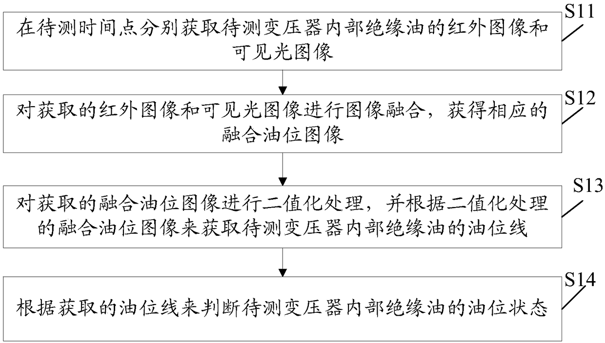
[0045] An embodiment of the present invention provides a method for detecting the oil level state of a transformer, which is suitable for monitoring the oil level state of the insulating oil in the transformer, see figure 1 , the method can include:

[0046] In step S11, the infrared image and the visible light image of the insulating oil inside the transformer to be tested are acquired respectively at the time point to be tested.

[0047] In this embodiment, the infrared image and the visible light image of the insulating oil inside the transformer to be tested can be respectively obtained through the peep window of the oil level indicator of the transformer to be tested. Of course, it should be noted that the infrared image and the visible light image are at the same position, The images were taken at the same angle and at short time intervals for subsequent image fusion.

[0048] Step S12, performing image fusion on the acquired infrared image and visible light image to ob...

Embodiment 2

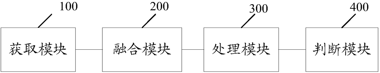
[0075] An embodiment of the present invention provides a transformer oil level detection device, which implements the method described in Embodiment 1, see image 3 , the device may include: an acquisition module 100 , a fusion module 200 , a processing module 300 , and a judging module 400 .

[0076] The acquisition module 100 is configured to respectively acquire an infrared image and a visible light image of the insulating oil inside the transformer to be tested at the time point to be tested.

[0077] In this embodiment, the infrared image and the visible light image of the insulating oil inside the transformer to be tested can be respectively obtained through the peep window of the oil level indicator of the transformer to be tested. Of course, it should be noted that the infrared image and the visible light image are at the same position, The images were taken at the same angle and at short intervals for subsequent image fusion.

[0078] The fusion module 200 is configu...


PUM


Abstract

The invention discloses an oil level state detection method and device of a transformer. The method includes the steps of separately obtaining infrared images and visible light images of internal insulating oil in the to-be-detected transformer at a to-be-detected time point; conducting image fusion on the obtained infrared images and visible light images to obtain corresponding fusion oil level images; conducting binarization processing on the obtained fusion oil level images, and obtaining an oil level line of the internal insulating oil of the to-be-detected transformer according to the fusion oil level images subjected to binarization processing; according to the obtained oil level line, judging the oil level state of the internal insulating oil of the to-be-detected transformer. The provided oil level state detection method achieves automatic monitoring of the oil level state of the transformer in real time according to the fusion oil level images, correspondingly a user can knowabout the oil level state of the transformer in real time, the manpower resource consumed for manual inspection is avoided, a monitoring result of the oil level state is accurate and reliable, and safe and stable running of a power system is guaranteed.

Description

technical field [0001] The invention relates to the technical field of oil level detection, in particular to a method and device for detecting the oil level state of a transformer. Background technique [0002] The insulating oil inside the transformer has a much higher dielectric strength than air, has a good cooling effect, and is a good arc-extinguishing medium. safe operation. [0003] At present, the oil level monitoring of transformers still adopts the method of manual inspection. This method cannot monitor the oil level status around the clock, and cannot grasp the oil level status in real time, which has certain potential safety hazards. Therefore, real-time monitoring of the oil level status is extremely important for the safe and stable operation of the power system. Contents of the invention [0004] In order to solve the problems in the prior art, embodiments of the present invention provide a method and device for detecting the oil level state of a transform...

Claims


Application Information

Patent Timeline
Patent Type & Authority Applications(China)
IPC IPC(8): G01F23/292
CPCG01F23/292
Inventor 余里程宁柏锋吕志宁庞宁黄安子冯薇玺孙蓉蓉夏伟杨育
Owner SHENZHEN POWER SUPPLY BUREAU
Why Eureka
Try Eureka