Supersonic velocity integrated spray pipe design method

A design method and supersonic technology, applied in the field of wind tunnel test, can solve the problems of small test uniform zone area, small nozzle exit Mach angle, increase of wind tunnel operation cost, etc., and achieve the effect of excellent flow field quality and continuous slope

Active Publication Date: 2018-06-19
CHINA ACAD OF AEROSPACE AERODYNAMICS
View PDF7 Cites 8 Cited by
  • Summary
  • Abstract
  • Description
  • Claims
  • Application Information

AI Technical Summary

Problems solved by technology

[0002] At present, in the supersonic wind tunnel test, due to the small Mach angle at the exit of the nozzle, the effective test uniform area is small. In order to avoid the test model being exposed outside the test uniform area, only a small test model can be used.
There is a certain deviation between the test d

Method used


Image

  • Supersonic velocity integrated spray pipe design method
  • Supersonic velocity integrated spray pipe design method
  • Supersonic velocity integrated spray pipe design method

Examples


Embodiment Construction

[0034] Below in conjunction with accompanying drawing and specific embodiment the present invention is described in further detail:

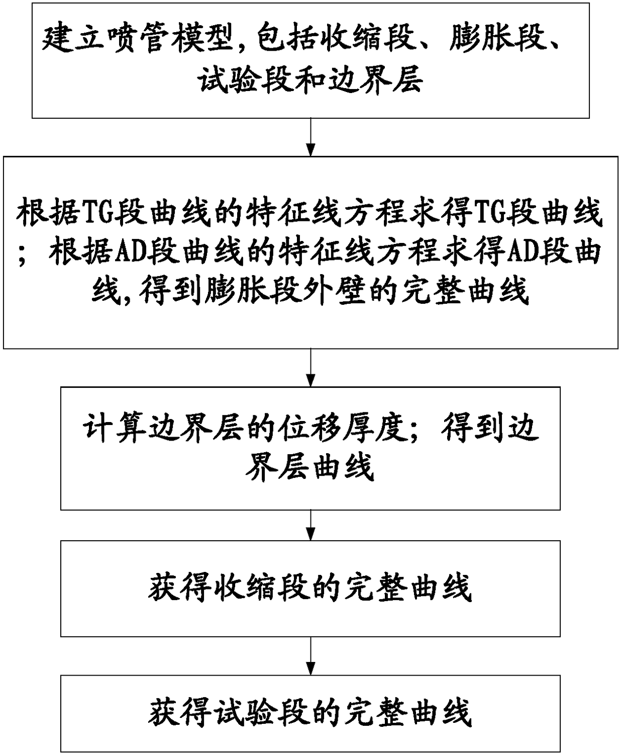
[0035] Such as figure 2 Shown is a schematic diagram of the supersonic integrated nozzle design process. It can be seen from the figure that a supersonic integrated nozzle design method includes the following steps:

[0036] Step (1), establishing the nozzle model; including contraction section 1, expansion section 2, test section 3 and boundary layer 4; wherein, contraction section 1, expansion section 2 and test section 3 are connected end-to-end in the axial direction; boundary layer 4 Coated on the outer wall of the expansion section 2 and the test section 3; the connection between the contraction section 1 and the expansion section 2 is a throat; as figure 1 Shown is a schematic diagram of the supersonic integrated nozzle. It can be seen from the figure that the position of the throat corresponding to the outer wall of the nozzle is point...


PUM


Abstract

The invention discloses a supersonic velocity integrated spray pipe design method and relates to the field of wind tunnel tests. The method includes the following steps of 1, creating a spray pipe model, wherein the model includes a retraction segment, an expansion segment, a testing segment and a boundary layer; 2, figuring out a TG segment curve according to a characteristic line equation of theTG segment curve, figuring out an AD segment curve according to a characteristic line equation of the AD segment curve, and correspondingly obtaining a complete curve of the outer wall of the expansion segment; 3, calculating the displacement thickness of the boundary layer to obtain a boundary layer curve; 4, obtaining a complete curve of the retraction segment; 5, obtaining a complete curve ofthe testing segment. By means of the method, a testing area is enlarged, and the parameters such as a Mach number root-mean-square deviation, an axial Mach number gradient and an airflow-deviation angle of the testing segment are all in line with national military-standard advanced indexes.

Description

technical field [0001] The invention relates to the field of wind tunnel tests, in particular to a supersonic integrated nozzle design method. Background technique [0002] At present, in the supersonic wind tunnel test, due to the small Mach angle at the exit of the nozzle, the effective test uniform area is small. In order to avoid the test model being exposed outside the test uniform area, only a small test model can be used. There is a certain deviation between the test data obtained in the wind tunnel of the small test model and the test data obtained by the actual aircraft model, which affects the test accuracy. At the same time, the small uniform area of ​​the test limits the continuous change of the attitude angle of the model and increases the operating cost of the wind tunnel. Contents of the invention [0003] The purpose of the present invention is to overcome the above-mentioned deficiencies in the prior art, and provide a supersonic integrated nozzle design ...

Claims


Application Information

Patent Timeline
IPC IPC(8): G06F17/50G06F17/11
CPCG06F17/11G06F30/17G06F30/20G06F2119/18
Inventor 谌君谋陈星李广良张江李睿劬秦永明
Owner CHINA ACAD OF AEROSPACE AERODYNAMICS
Why Eureka
Try Eureka