Transporting and erecting integrated bridge girder erection machine of rear cart three rows of tires

A kind of bridge erecting machine and integrated technology, which is applied in the field of integrated bridge erecting machine, which can solve the problems of increased length and weight of the whole machine, unfavorable construction load and operability of the rigidity of the main girder, and achieve the goal of the main girder Effects of weight reduction, easy-to-see adjustments, and shortened girder length

Pending Publication Date: 2018-06-26
TAIYUAN UNIVERSITY OF SCIENCE AND TECHNOLOGY
View PDF0 Cites 1 Cited by
  • Summary
  • Abstract
  • Description
  • Claims
  • Application Information

AI Technical Summary

Problems solved by technology

For example: for a typical type of bridge erecting machine, as the length of the concrete box girder increases, the length of the main girder also increases, which will increase the length and weight of the bridge erecting machine. The rigidity of the main girder, carrying the girder through the tunnel, and the construction load and operability of the erected girder are all unfavorable

Method used


Image

  • Transporting and erecting integrated bridge girder erection machine of rear cart three rows of tires
  • Transporting and erecting integrated bridge girder erection machine of rear cart three rows of tires
  • Transporting and erecting integrated bridge girder erection machine of rear cart three rows of tires

Examples


Embodiment Construction

[0028] The technical solutions of the present invention will be clearly and completely described below in conjunction with the accompanying drawings, and it is obvious that the described embodiments are part of the embodiments of the present invention, but not all of them. Based on the embodiments of the present invention, all other embodiments obtained by persons of ordinary skill in the art without making creative efforts belong to the protection scope of the present invention.

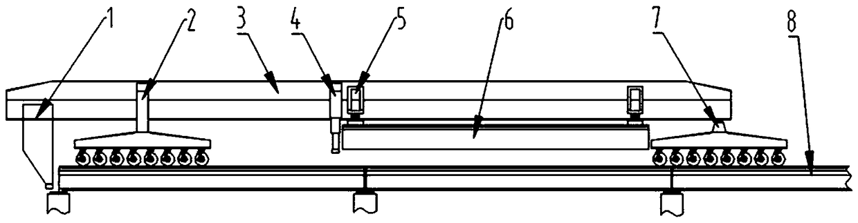
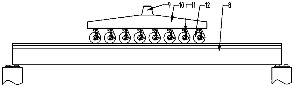
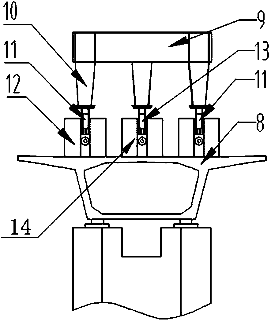
[0029] Such as Figure 1 ~ Figure 3 As shown, an integrated bridge erecting machine for transporting and erecting a frame with three rows of tires for rear cars 7, including a main girder 3, a main outrigger 1 is provided at the bottom of one side of the main girder 3, and an auxiliary support is provided in the center of the main girder 3 Leg 4, the bottom of the main beam 3 on the side of the main leg is provided with a front car 2, and the bottom of the other side of the main beam 3 is provided w...


PUM


Abstract

The invention provides a transporting and erecting integrated bridge girder erection machine of rear cart three rows of tires. The transporting and erecting integrated bridge girder erection machine comprises a main beam, a front vehicle, a rear vehicle, a main support, a subsidiary support and a hanging beam crown block; the rear cart comprises a rear cart cross beam connected to the bottom of the main beam, rear cart longitudinal beams are arranged at the bottoms of the two sides of the rear cart cross beam, the bottoms of the middles of the rear cart longitudinal beams are connected to rearcart middle-row wheels through rear cart middle-row wheel set hanging hydraulic cylinders, the bottoms of the rear cart longitudinal beams are connected to rear cart two-side wheels through rear carttwo-side wheel set hanging hydraulic cylinders respectively, the rear cart middle-row wheel set hanging hydraulic cylinders and the rear cart two-side wheel set hanging hydraulic cylinders are connected to the output ends of hydraulic pumps through hydraulic pipes respectively, the input ends of the hydraulic pumps are connected to an engine through a reduction box, and the hydraulic pipes are provided with pressure regulating valves respectively. Through the transporting and erecting integrated bridge girder erection machine of the rear cart three rows of tires, the problems are solved thatas the lengths of concrete box girders increase, existing bridge girder erection machines are disadvantageous to main beam rigidity, construction load of a subsidiary beam passing a tunnel and an erected bridge and operability.

Description

technical field [0001] The invention relates to a bridge erecting machine, in particular to an integrated bridge erecting machine for transporting three rows of tires on a rear vehicle. Background technique [0002] With the continuous development of my country's railways, the spans of prefabricated bridge piers erected on railway routes are getting larger and larger, and the length of erected concrete box girders is also increasing, and the requirements for bridge erecting machines are also getting higher and higher. For example: for a typical type of bridge erecting machine, as the length of the concrete box girder increases, the length of the main girder also increases, which will increase the length and weight of the bridge erecting machine. The rigidity of the main girder, carrying the girder through the tunnel, and the construction load and operability of the erected girder are all unfavorable. Contents of the invention [0003] The invention solves the deficiencies...

Claims


Application Information

Patent Timeline
Patent Type & Authority Applications(China)
IPC IPC(8): E01D21/00
CPCE01D21/00
Inventor 徐格宁焦国敏戚其松董青王嵽显
Owner TAIYUAN UNIVERSITY OF SCIENCE AND TECHNOLOGY
Why Eureka
Try Eureka