Pulling and erecting method of truss girder

A truss girder, hauling technology, applied in bridge construction, erection/assembly of bridges, bridges, etc., can solve the problems of great influence of environmental factors, great influence by wind, increase operation danger, etc., so as to reduce aerial work and water work, The effect of shortening the construction period and being conducive to safe construction

Active Publication Date: 2013-01-23
CHINA RAILWAY 23RD CONSTR BUREAU LTD +1
View PDF6 Cites 7 Cited by
  • Summary
  • Abstract
  • Description
  • Claims
  • Application Information

AI Technical Summary

Problems solved by technology

Using this method to erect steel truss girders has the following problems: (1) This erection method requires a high sling tower, which is greatly affected by the wind and is not suitable for use in strong wind areas. In addition, the assembled sling tower It belongs to the high-altitude operation itself, and the assembly period is long; (2), because the sling tower needs to provide a large upward pulling force of the cantilever of the steel truss beam, and needs to be symmetrically cable-stayed front and rear, the tower needs to bear double the vertical pressure and force If the vertical height and rigidity requirements are met at the same time, the steel tower structure will become larger and the cost will increase; (3) When the current hole beam is erected by the sling tower and the next hole beam is erected, if the single For the cantilever method, the tower needs to be moved forward by one hole. If the double cantilever method is used, the tower must be dismantled and transferred to the top of the next pier for reassembly. Because the sling tower itself is relatively large, it is difficult to move or install, It is more difficult to disassemble, and it also increases the risk of operation
When the method of cantilever assembly and temporary pier erection is adopted, there are also the following problems: (1) The temporary pier uses the bearing capacity of the foundation as the reaction force to provide the upward support force of the cantilever end of the steel truss beam, but the temporary pier is affected by the environment Factors have a great influence, especially on soft foundations or the construction of temporary piers on rivers, lakes and seas requires a lot of investment, and is also limited by shipping conditions, so it is not suitable to build temporary piers; resulting in high cost and waste
However, because this method adopts longitudinal dragging, it is difficult to control the lateral dimension, so this method is only suitable for the erection of straight bridges, and this method cannot be applied to bridges that are not straight, especially bridges with small bending radii. The method drags the truss girder. With the increase of the length of the truss girder, the jack is required to provide greater power, which increases the performance requirements of the jack and the steel strand.

Method used


Image

  • Pulling and erecting method of truss girder
  • Pulling and erecting method of truss girder
  • Pulling and erecting method of truss girder

Examples


Embodiment 1

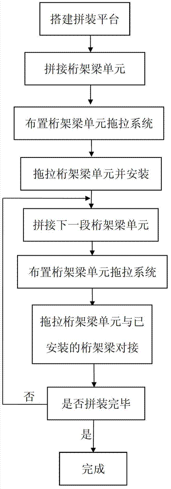
[0048] In this embodiment, the truss beam is divided into 11 truss beam units, such as figure 1 The drag-and-drag erection method of the truss girder shown is to divide the truss girder into several sections according to the shape of the bridge in the actual project, and ensure that the truss girder segments obtained after the truss girder segments are connected in turn meet the design requirements as a whole;

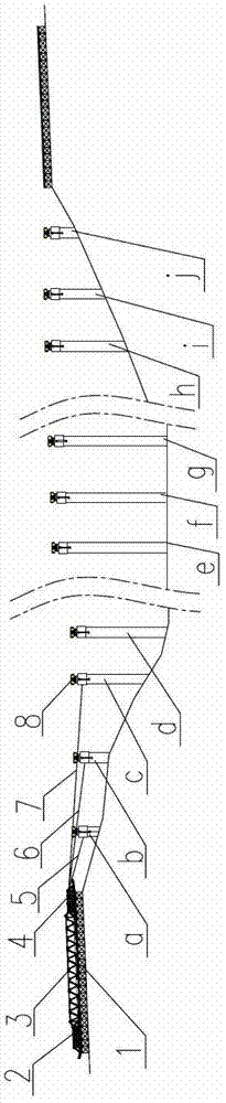
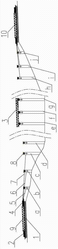
[0049] like figure 2 As shown, the assembly platform 1 of the truss beam unit is respectively built on the two banks corresponding to the bridge pier, and a slideway is set on the platform of the assembly platform 1, and the first section of the truss beam unit 3 is spliced ​​on the assembly platform 1 according to the segmental requirements, and then Place it on the slideway, install the front guide beam 2 and the rear guide beam 4 at both ends of the truss beam unit 3, and then arrange a set of continuous jacks on each auxiliary truss beam unit, and arrange steel s...


PUM


Abstract

The invention discloses a pulling and erecting method of a truss girder. According to the shape of a bridge in an actual project, a truss girder is separated into several sections, then every truss girder unit is pulled and dragged in order and abutted one by one; at last, the whole truss girder is obtained. For the integrative truss girder obtained by a segmental pulling and abutting manner, the erection of a flat upright truss girder can be satisfied while the erection of the truss girder with a small curve radius also can be satisfied; meanwhile, for the truss girder can be assembled on a bracket on a shore, the truss girder can be assembled and welded, thereby the time limit is effectively shortened; by assembling a steel truss girder on the bracket on the shore, the overhead work and the water work are reduced, thus being beneficial to safe construction; and furthermore, the construction of both ends of the truss girder is realized at the same time, the work limit is effectively shortened.

Description

technical field [0001] The invention relates to a method for erecting a truss beam, in particular to a method for dragging and erecting a truss beam. Background technique [0002] With the development of economy and technology, more and more truss bridges need to be built. When crossing rivers and canyons, truss bridges with large spans and multiple continuous spans are usually used. At present, the erection of truss bridges is generally carried out by splicing. This construction method has a long construction period, especially in the rainy season and winter, and the welding quality of steel truss beams is not easy to guarantee. Therefore, in order to improve the quality of rigid truss erection and shorten the construction period, construction workers generally assemble steel beams on shore supports as much as possible to achieve factory production operations, avoiding welding of steel truss beams and tightening high-strength bolts due to rainy seasons and winter However, ...

Claims


Application Information

Patent Timeline
Patent Type & Authority Applications(China)
IPC IPC(8): E01D21/00
Inventor 田宝华李治强彭继安陈幼林杨毅刘延龙王岑申瑞烂周建新巨建基王红徐仁华杨肃钟张晓飞霍莉董凤杰周川岭樊建国
Owner CHINA RAILWAY 23RD CONSTR BUREAU LTD
Why Eureka
Try Eureka