Improved dust collector equipment

A dust collector, an improved technology, applied in the direction of chemical instruments and methods, cleaning methods and appliances, etc., can solve the problems of exposed electrical outlets, potential safety hazards, etc., to increase the safety of use, stable and safe operation, and reduce accidental electric shock accidents Effect

Inactive Publication Date: 2018-06-29
韦龙生
View PDF7 Cites 0 Cited by
  • Summary
  • Abstract
  • Description
  • Claims
  • Application Information

AI Technical Summary

Problems solved by technology

[0002] Dust collectors are commonly used vacuuming equipment in people’s daily life. At present, the power-on of the dust collector is mainly to insert the plug connected to the dust collector into the power outlet of the power transmission socket and clamp it. Although this clamping method is simple to operate, it is The lead port of the power transmission base will always be connected to the mains. When the dust collector is not in use, the plug is often pulled out from the lead port, which will cause the lead port to be exposed. Since there is no setting outside the lead port Any protective parts, so there is a greater potential safety hazard

Method used


Image

  • Improved dust collector equipment
  • Improved dust collector equipment
  • Improved dust collector equipment

Examples


Embodiment Construction

[0022] The preferred embodiments of the present invention will be described in detail below in conjunction with the accompanying drawings, so that the advantages and features of the present invention can be more easily understood by those skilled in the art, so as to define the protection scope of the present invention more clearly.

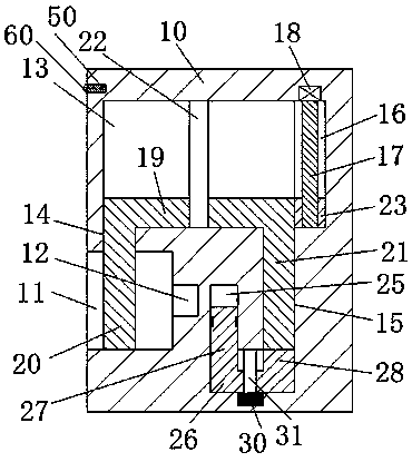
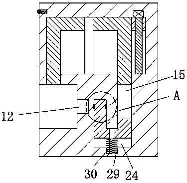
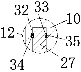
[0023] refer to Figure 1-4 As shown, an improved dust collector device of the present invention includes a power transmission base 10, four corners of the bottom end surface of the power transmission base 10 are fixedly installed with feet 101, and the bottom of the feet 101 is rollingly installed with rollers 102 , the left end surface of the power transmission seat 10 is provided with a plug-and-pull chamber 11, and the right end wall of the plug-pull chamber 11 is provided with an electric port 12, and the power transmission seat 10 is provided with a sliding chamber 13, and the sliding The front end wall on the left side of the cavity 13 is ...


PUM


Abstract

The invention discloses improved dust collector equipment. The improved dust collector equipment comprises a transmission base, wherein stilts are fixedly mounted at four vertex angles on the bottom end surface of the transmission base; rollers are mounted in the bottoms of the stilts in a rolling manner; an inserting-pulling cavity is formed in the left end surface of the transmission base; and an electricity guiding port is formed in the right end wall of the inserting-pulling cavity. The improved dust collector equipment is characterized in that a sliding conveying cavity is formed in the transmission base; a connecting hole communicating to the sliding conveying cavity is formed in the front end wall of the left side of the sliding conveying cavity; an inserting-pulling slot extendingforward is formed in the front end wall of the right side of the sliding conveying cavity; and a driving cavity communicating to the sliding conveying cavity is formed in the right end wall of the sliding conveying cavity. The improved dust collector equipment disclosed by the invention is simple in integral structure, simple and convenient to interrupt and electrify and close and open the electricity guiding port, and can be achieved by one motor, so that electric shock accidents are reduced effectively, the life safety of people is guaranteed effectively, and the improved dust collector equipment is low in production and manufacturing cost and suitable for popularized and applied.

Description

technical field [0001] The invention relates to the field of dust collectors, in particular to an improved dust collector equipment. Background technique [0002] Dust collectors are commonly used vacuuming equipment in people’s daily life. At present, the power-on of the dust collector is mainly to insert the plug connected to the dust collector into the power outlet of the power transmission socket and clamp it. Although this clamping method is simple to operate, it is The lead port of the power transmission base will always be connected to the mains. When the dust collector is not in use, the plug is often pulled out from the lead port, which will cause the lead port to be exposed. Since there is no setting outside the lead port Any protective parts, so there is a greater potential safety hazard. Contents of the invention [0003] The technical problem to be solved by the present invention is to provide an improved dust collector device, which can solve the above-menti...

Claims


Application Information

Patent Timeline
Patent Type & Authority Applications(China)
IPC IPC(8): B08B13/00
CPCB08B13/00
Inventor 韦龙生
Owner 韦龙生
Why Eureka
Try Eureka