Novel new-energy automobile equipment

A new energy vehicle and equipment technology, applied in the direction of electric vehicles, electric vehicle charging technology, vehicle energy storage, etc., can solve the problems of potential safety hazards, exposure of the power cavity, etc., and achieve stable and safe operation, increase the safety of use, and easy operation Effect

Inactive Publication Date: 2018-02-23
叶维
View PDF6 Cites 0 Cited by
  • Summary
  • Abstract
  • Description
  • Claims
  • Application Information

AI Technical Summary

Problems solved by technology

[0002] With the country's vigorous promotion of energy conservation and environmental protection, more and more new energy vehicles are used. Before using new energy vehicles, the batteries in new energy vehicles need to be charged. At present, the charging of new energy vehicles is The connected charging gun is inserted into the charging cavity of the charging part and clamped tightly. Although this clamping method is simple to operate, the connecting cavity of the charging part and the mains will always be in a power-on state. When the new energy vehicle is not charging, the charging The gun is often pulled out from the UMC cavity, which will result in the exposure of the UMC cavity. Since there are no protective parts outside the UMC cavity, there is a great potential safety hazard

Method used


Image

  • Novel new-energy automobile equipment
  • Novel new-energy automobile equipment
  • Novel new-energy automobile equipment

Examples


Embodiment Construction

[0023] The preferred embodiments of the present invention will be described in detail below with reference to the accompanying drawings, so that the advantages and features of the present invention can be more easily understood by those skilled in the art, and the protection scope of the present invention can be more clearly defined.

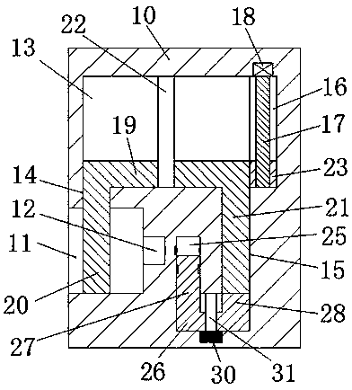
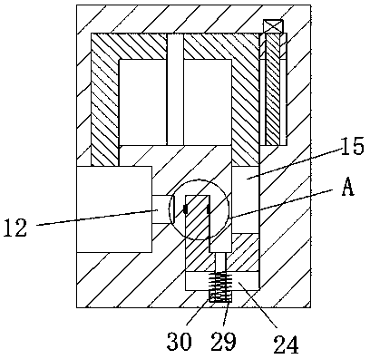
[0024] see Figure 1-5 As shown, a new type of new energy vehicle equipment of the present invention includes a charging pile body 100 and a charging portion 10 fixedly installed at the upper left end of the charging pile body 100, and a base 101 is also fixedly installed on the bottom end surface of the charging pile body 100 , the left end surface of the charging part 10 is provided with an insertion cavity 11, the right end wall of the insertion cavity 11 is provided with a junction cavity 12, and the charging part 10 is provided with a sliding cavity 13, the sliding cavity 13 The left front wall is provided with a connecting cavity 14 commun...


PUM


Abstract

The invention discloses novel new-energy automobile equipment which comprises a charging pile and a charging portion fixedly mounted at the left upper end of the charging pipe. A base is fixedly mounted on the bottom end face of the charging pile body, an inserting cavity is arranged on the left end face of the charging portion, and an electricity connecting cavity is arranged on the right end wall of the inserting cavity. The novel new-energy automobile equipment is characterized in that a sliding cavity is arranged in the charging portion, a connection cavity communicated with the sliding cavity is arranged on the front end wall of the left side of the sliding cavity, an inserting groove extending forwards is formed in the front end wall of the right side of the sliding cavity, and a movement driving cavity communicated with the sliding cavity is arranged in the right end wall of the sliding cavity. The novel new-energy automobile equipment is simple in integral structure and simpleand convenient in operation of powering off, powering on, closing and opening the electricity connecting cavity; the operation can be realized through only one driver, so that accidental electric shock accidents are reduced effectively, and life safety of people is ensured effectively; the novel new-energy automobile equipment is low in producing and manufacturing cost and suitable for popularization and use.

Description

technical field [0001] The invention relates to the field of new energy vehicles, in particular to a new type of new energy vehicle equipment. Background technique [0002] With the country's vigorous promotion of energy conservation and environmental protection, the use of new energy vehicles is increasing. Before new energy vehicles are used, the batteries in new energy vehicles need to be charged. At present, the charging of new energy vehicles is mainly related to new energy vehicles. The connected charging gun is inserted into the power supply cavity of the charging part and clamped. Although this way of clamping is simple, the connection between the power supply cavity of the charging part and the mains will always be in a power-on state. When the new energy vehicle is not charging, it will be charged. The gun is often pulled out from the joint power cavity, which will cause the joint power cavity to be exposed. Since there is no protective component outside the joint ...

Claims


Application Information

Patent Timeline
IPC IPC(8): B60L11/18
CPCB60L53/16B60L53/31Y02T10/70Y02T10/7072Y02T90/12Y02T90/14
Inventor 叶维
Owner 叶维
Why Eureka
Try Eureka