Method for measuring downlink channel state information, base station and terminal
A channel state information and measurement method technology, applied in the downlink channel state information measurement method, base station and terminal field, can solve the problems of prolonged measurement time, inability to realize beam fast switching, etc., and achieve the effect of reducing measurement delay
- Summary
- Abstract
- Description
- Claims
- Application Information
AI Technical Summary
Problems solved by technology
Method used
Image
Examples
no. 1 example
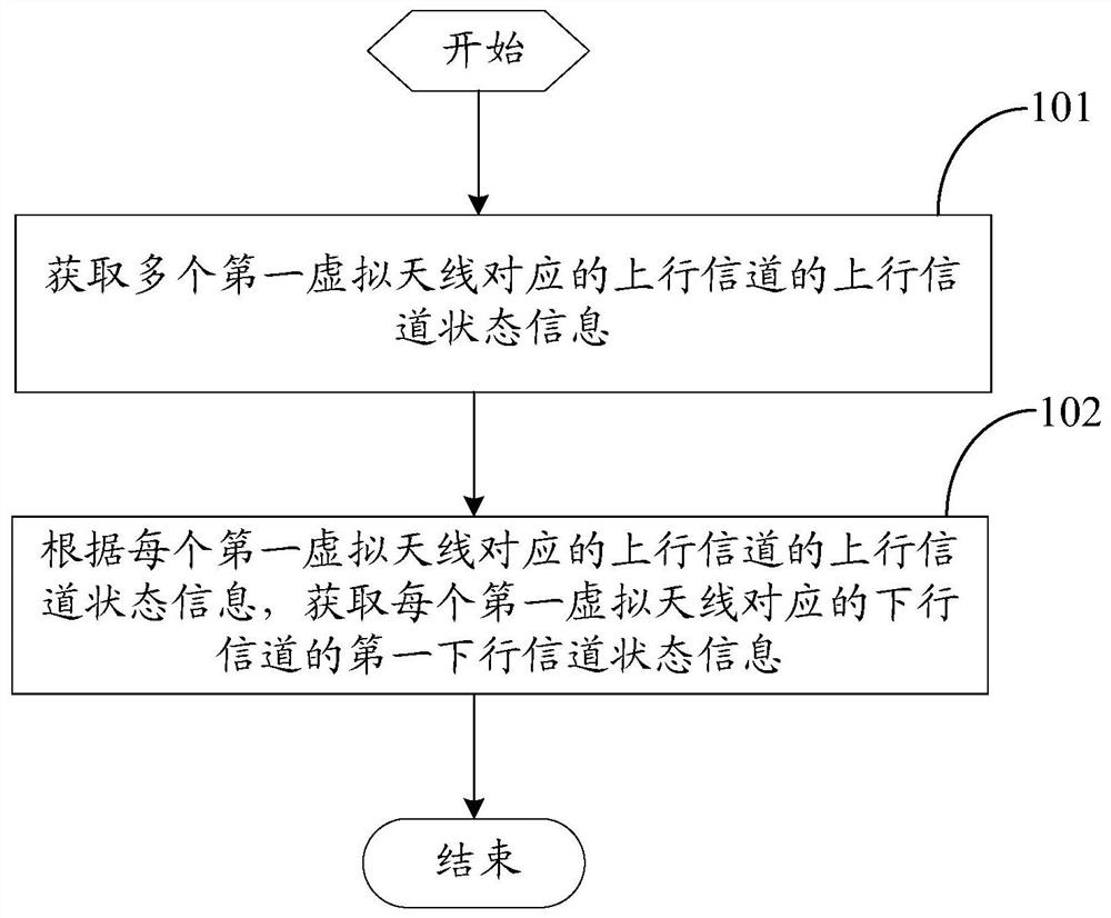
[0032] Such as figure 1 As shown, the first embodiment of the present invention provides a method for measuring downlink channel state information, which is applied to a base station, and the method includes:
[0033] Step 101, acquiring uplink channel state information of uplink channels corresponding to multiple first virtual antennas.
[0034] Wherein, the above-mentioned uplink channel state information may be received quality (RSRQ) or received power (RSRP) of the uplink pilot signal sent by the terminal. In addition, the above-mentioned multiple first virtual antennas may be multiple first virtual antennas of the above-mentioned base station, or multiple first virtual antennas of neighboring base stations of the base station, and which base station the multiple first virtual antennas specifically belong to, It will be described in detail later.
[0035] In the embodiment of the present invention, in order to facilitate the understanding of the above method, the meaning...
no. 2 example
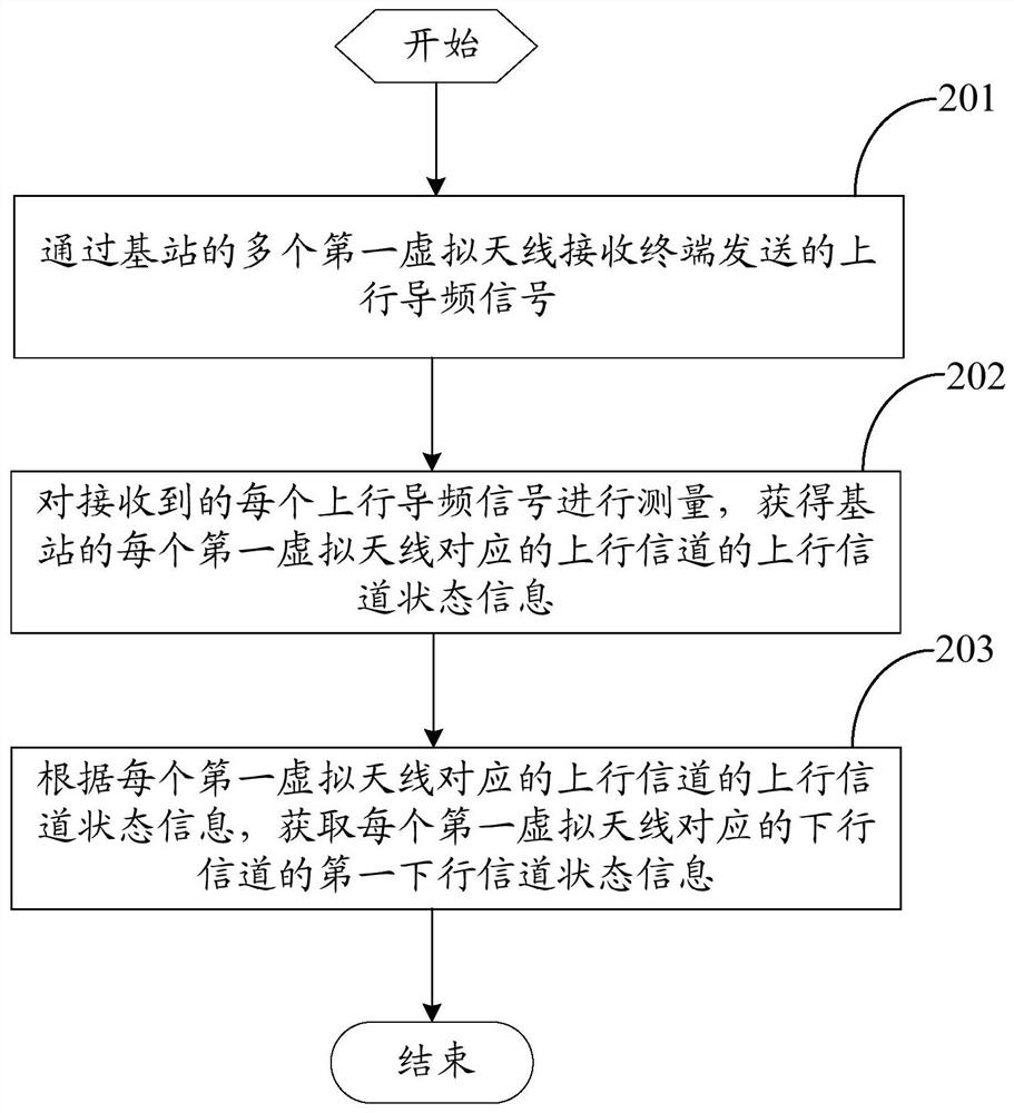
[0041] Such as figure 2 As shown, the second embodiment of the present invention provides a method for measuring downlink channel state information, which is applied to a base station, and the method includes:
[0042] Step 201: Receive an uplink pilot signal sent by a terminal through multiple first virtual antennas of a base station.
[0043]Wherein, each first virtual antenna of the base station receives an uplink pilot signal sent by the terminal, such as a channel sounding reference signal (SRS, Sounding Reference Signal).
[0044] Wherein, in the second embodiment of the present invention, before performing the above step 201, the above method further includes the following step: sending to the terminal the first configuration information of the terminal sending the uplink pilot signal. Wherein, the first configuration information includes the time-frequency position where the terminal sends the uplink pilot signal. In this way, the base station can identify the ident...
no. 3 example
[0068] The above first embodiment to the second embodiment respectively introduce the measurement methods of the downlink channel state information in different scenarios in detail, and the following will combine Figure 4 The base station corresponding to it is further introduced.
[0069] Such as Figure 4 As shown, the third embodiment of the present invention provides a base station, and the base station 400 includes:
[0070] The first acquiring module 401 is configured to acquire uplink channel state information of uplink channels corresponding to a plurality of first virtual antennas;
[0071] The second obtaining module 402 is configured to obtain the first downlink channel state information of the downlink channel corresponding to each first virtual antenna according to the uplink channel state information of the uplink channel corresponding to each first virtual antenna.
[0072] Optionally, the first acquisition module 401 includes:
[0073] The first acquisition...
PUM
 Abstract
Description
Claims
Application Information
 - R&D
- Intellectual Property
- Life Sciences
- Materials
- Tech Scout
- Unparalleled Data Quality
- Higher Quality Content
- 60% Fewer Hallucinations
Browse by: Latest US Patents, China's latest patents, Technical Efficacy Thesaurus, Application Domain, Technology Topic, Popular Technical Reports.
© 2025 PatSnap. All rights reserved.Legal|Privacy policy|Modern Slavery Act Transparency Statement|Sitemap|About US| Contact US: help@patsnap.com


