Method, device, base station and user equipment for realizing beam optimization
A beam optimization and beam technology, applied in wireless communication, electrical components, network planning, etc., can solve problems such as long measurement delay, large overhead, low RACH resource utilization, etc., to reduce measurement delay, reduce overhead, improve Effect of RACH resource utilization
- Summary
- Abstract
- Description
- Claims
- Application Information
AI Technical Summary
Problems solved by technology
Method used
Image
Examples
Embodiment 1
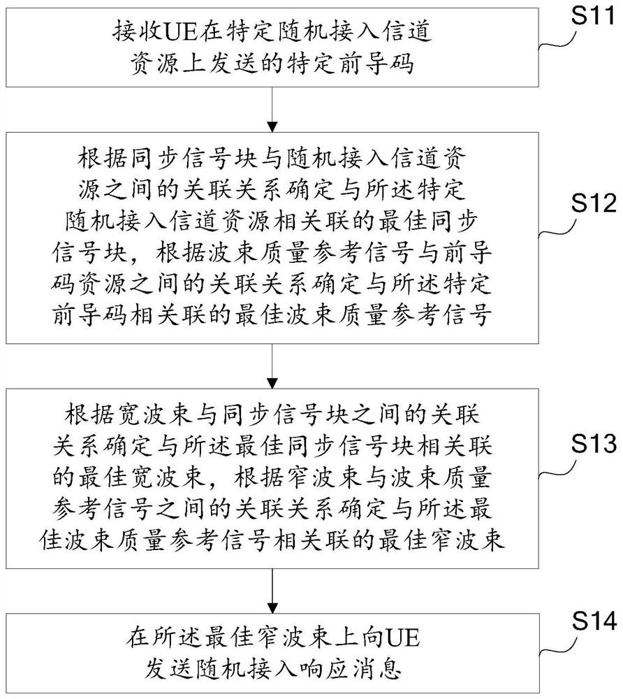
[0098] Three synchronization signal blocks are configured on the base station side, namely: synchronization signal block A, synchronization signal block B, and synchronization signal block C. Each synchronization signal block can reflect the quality of a wide beam of the base station. The base station is configured with 12 beam quality reference signals, and each beam quality reference signal can reflect the quality of a narrow beam of the base station. Each sync signal block is associated with four beam quality reference signals (sync signal block A is associated with beam quality reference signal A1, beam quality reference signal A2, beam quality reference signal A3, beam quality reference signal A4, sync signal block B is associated with beam quality Quality reference signal B1, beam quality reference signal B2, beam quality reference signal B3, beam quality reference signal B4, synchronization signal block C associated beam quality reference signal C1, beam quality referenc...
Embodiment 2
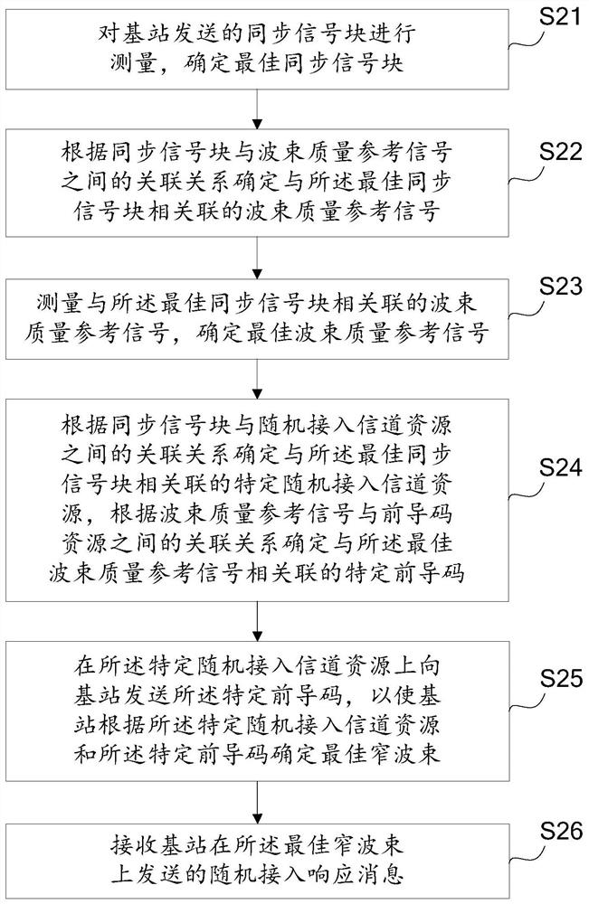
[0116] Three synchronization signal blocks are configured on the base station side, namely: synchronization signal block A, synchronization signal block B, and synchronization signal block C. Each synchronization signal block can reflect the quality of a wide beam of the base station. The base station is configured with 12 beam quality reference signals, and each beam quality reference signal can reflect the quality of a narrow beam of the base station. Each sync signal block is associated with four beam quality reference signals (sync signal block A is associated with beam quality reference signal A1, beam quality reference signal A2, beam quality reference signal A3, beam quality reference signal A4, sync signal block B is associated with beam quality Quality reference signal B1, beam quality reference signal B2, beam quality reference signal B3, beam quality reference signal B4, synchronization signal block C associated beam quality reference signal C1, beam quality referenc...
Embodiment 3
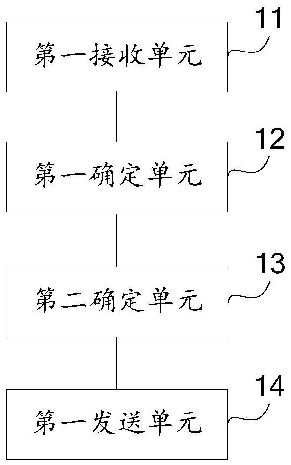
[0134] Three synchronization signal blocks are configured on the base station side, namely: synchronization signal block A, synchronization signal block B, and synchronization signal block C. Each synchronization signal block can reflect the quality of a wide beam of the base station. The base station is configured with 12 beam quality reference signals, and each beam quality reference signal can reflect the quality of a narrow beam of the base station. Each sync signal block is associated with four beam quality reference signals (sync signal block A is associated with beam quality reference signal A1, beam quality reference signal A2, beam quality reference signal A3, beam quality reference signal A4, sync signal block B is associated with beam quality Quality reference signal B1, beam quality reference signal B2, beam quality reference signal B3, beam quality reference signal B4, synchronization signal block C associated beam quality reference signal C1, beam quality referenc...
PUM
 Abstract
Description
Claims
Application Information
 - R&D
- Intellectual Property
- Life Sciences
- Materials
- Tech Scout
- Unparalleled Data Quality
- Higher Quality Content
- 60% Fewer Hallucinations
Browse by: Latest US Patents, China's latest patents, Technical Efficacy Thesaurus, Application Domain, Technology Topic, Popular Technical Reports.
© 2025 PatSnap. All rights reserved.Legal|Privacy policy|Modern Slavery Act Transparency Statement|Sitemap|About US| Contact US: help@patsnap.com


