Roller type refrigerator liner double-short-side corner line step-by-step riveting mechanism

A technology of freezer liner and corner line, which is applied in the field of automatic production line of freezer liner, which can solve the problems of low yield rate and achieve the effect of sufficient bending and improved yield rate

Active Publication Date: 2018-07-17
ANHUI KINGPOWER EQUIP & MOLD MFR
View PDF12 Cites 0 Cited by
  • Summary
  • Abstract
  • Description
  • Claims
  • Application Information

AI Technical Summary

Problems solved by technology

[0003] The problem to be solved by the present invention: In the step-by-step riveting of the side line of the bottom plate of the refrigerator liner, there are various problems in the step-by-step riveting mechanism of the double short side corner line of the freezer liner in the existing riveting equipment for the short side corner line of the freezer liner. low yield

Method used


Image

  • Roller type refrigerator liner double-short-side corner line step-by-step riveting mechanism
  • Roller type refrigerator liner double-short-side corner line step-by-step riveting mechanism
  • Roller type refrigerator liner double-short-side corner line step-by-step riveting mechanism

Examples


Embodiment Construction

[0026] The present invention will be described in further detail below in conjunction with the accompanying drawings.

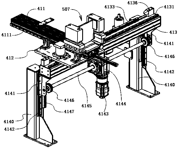
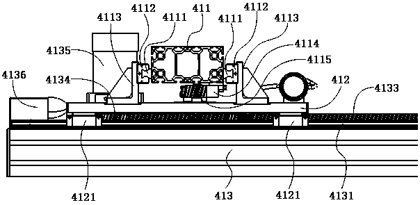
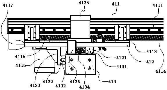
[0027] Such as Figure 11 shown. Figure 11 It is an upside-down freezer liner, wherein 5991 is a Z-shaped bottom plate, 5992 is a U-shaped large enclosure, and 5993 is a U-shaped small enclosure. U-shaped large coaming plate 5992 and U-shaped small coaming plate 5993 are mutually riveted to form a mouth-shaped coaming plate, and then the mouth-shaped coaming plate is riveted with a Z-shaped bottom plate 5991 to become a refrigerator liner. The step-by-step riveting mechanism for the double short side corners of the inner container of the roller type refrigerator in this embodiment is used for riveting the short side corners 5997 between the Z-shaped bottom plate 5991 and the U-shaped small surrounding board 5993 . There are two short side corner lines 5997.

[0028] A step-by-step riveting mechanism for double short side corner lines of a roller-type free...


PUM


Abstract

The invention discloses a roller-type refrigerator liner double-short-side corner line step-by-step riveting mechanism. The mechanism comprises a double-short-side corner line riveting mechanism and amechanical arm mechanism. The mechanical arm mechanism comprises a transverse movable mechanical arm and a longitudinal telescopic mechanical arm. The double-short-side corner line riveting mechanismis installed at the front end of the mechanical arm, wherein the double-short-side riveting support comprises a short side riveting support and two horizontal edge riveting mechanisms arranged on theshort side riveting support, and the two horizontal edge riveting mechanisms are opposite to each other. The horizontal edge riveting mechanism comprises a straight edge clamping mechanism and a straight edge pressing plate bending mechanism. The straight edge pressing plate bending mechanism comprises a straight edge pressing plate mold strip, a straight edge bending mold strip and a straight edge driving frame. The straight edge pressing plate mold strip is installed below the straight edge driving frame through a spring column mechanism. The straight edge bending mold strip is a roller horizontally arranged and installed on a rolling shaft below the straight edge driving frame. The straight edge bending mold strip is located on the inner side of the straight edge pressing plate mold strip and clings to the inner side of the straight edge pressing plate mold strip. The straight edge clamping mechanism is located on the inner side of the straight edge bending mold strip. The straightedge driving frame is driven by a driving air cylinder to ascend and descend. According to the mechanism, the product rate of finished products is improved.

Description

technical field [0001] The invention relates to an automatic production line for a refrigerator liner. Background technique [0002] The applicant submitted the application number 201711188554.9 on November 24, 2017, "A Riveting Equipment for Short Side Corner Lines of Freezer Liner". The short side angle line riveting equipment of the refrigerator liner relates to a step-by-step riveting mechanism for the double short side angle line of the freezer liner. The step-by-step riveting mechanism of double short side corner lines of the refrigerator liner is composed of a double short side corner line riveting mechanism and a mechanical arm mechanism. Wherein, the double short side angle line riveting mechanism includes a short side riveting support and two opposite horizontal side riveting mechanisms installed on the short side riveting support. The horizontal edge riveting mechanism includes a straight edge jaw mechanism and a straight edge platen bending mechanism. The stra...

Claims


Application Information

Patent Timeline
Patent Type & Authority Applications(China)
IPC IPC(8): B21D39/02B21D19/08B21D51/18
CPCB21D19/08B21D39/02B21D51/18
Inventor 陈安伟段宗军
Owner ANHUI KINGPOWER EQUIP & MOLD MFR
Why Eureka
Try Eureka