
Vibration damper having a hydraulic traction stop

A shock absorber, hydraulic shock absorber technology, used in shock absorbers, springs/shock absorbers, shock absorbers, etc., can solve problems such as trouble, and achieve the effect of increasing cost and simple manufacturing

Active Publication Date: 2018-07-17
VOLKSWAGEN AG
View PDF9 Cites 1 Cited by
  • Summary
  • Abstract
  • Description
  • Claims
  • Application Information

AI Technical Summary

Problems solved by technology

it's very troublesome

Method used


Image

  • Vibration damper having a hydraulic traction stop
  • Vibration damper having a hydraulic traction stop
  • Vibration damper having a hydraulic traction stop

Examples


Embodiment Construction

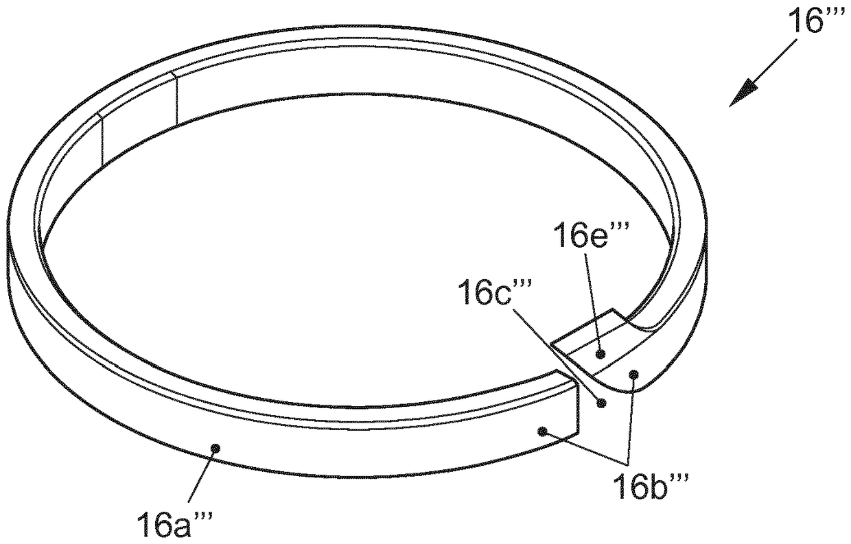
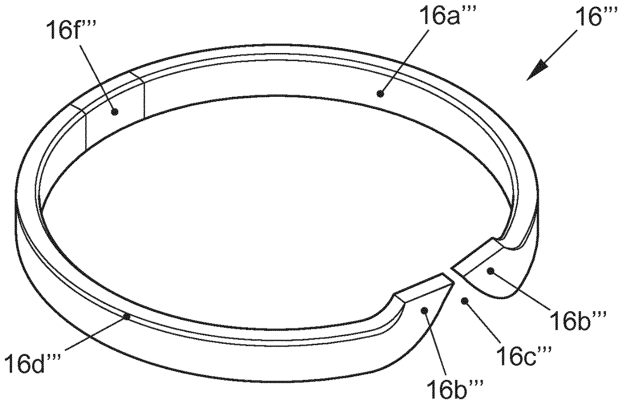
[0046] This exemplary embodiment and other embodiment variants relate to a vibration damper 1 with a hydraulic tension stop, which can be used in a wheel suspension of a motor vehicle.

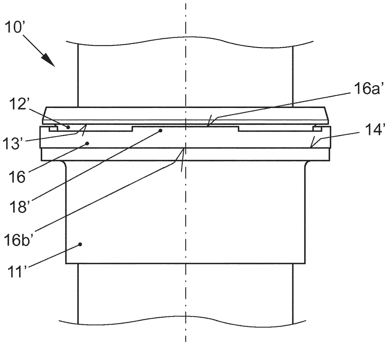
[0047] exist figure 1 shows an example of a vibration damper 1 with a container tube 2 into which a piston rod 3 is sunk. A piston 4 is fixed rigidly on the piston rod 3 , which divides the interior of the container tube 2 into two chambers 5 and 6 . The two chambers 5 and 6 form an upper working chamber and a lower working chamber of the vibration damper for receiving a hydraulic damping medium.

[0048] The vibration damper 1 also has a hydraulic damping device 10 , which can be used in single-tube shock absorbers as well as in double-tube shock absorbers, and will be explained in more detail below.

[0049] The hydraulic damping device 10 comprises a damping piston 11 for providing a hydraulic force directed opposite to the pulling movement of the piston rod 3 in the end region of the pis...


PUM


Abstract

The invention relates to a vibration damper having a hydraulic traction stop for a motor vehicle wheel suspension, comprising a reservoir tube (2"), a piston rod (3") and a hydraulic damping device (10") having a damping piston (11") fastened on the piston rod (3), which provides a hydraulic force directed against the tractive motion of the piston rod (3") in an end region of a piston rod extraction path before reaching the maximum piston rod extraction path. The damping piston (11") has a circumferential groove (12") in which a slotted sealing ring (16") is received, which hydraulically sealsin the groove (12") in said end region of the piston rod extraction path upon movement of the piston rod (3") in the traction direction and, upon movement of the piston rod (3") in the pressure direction at least locally rises from a flank (14") of the groove (12") on the pressure direction side, which delimits the groove (12") on the side in the pressure direction and in the traction direction,in order to provide a defined permeability for a hydraulic damping medium between the groove (12") and the sealing ring (16").

Description

technical field [0001] The invention relates to a vibration damper with a hydraulic pull stop for the wheel suspension of a motor vehicle, comprising a container tube, a piston rod and a hydraulic damper with a damper piston fastened to the piston rod , the damping device provides a hydraulic force directed opposite to the pulling movement of the piston rod in the end region of the piston rod pull-out path until the maximum piston rod pull-out path is reached, wherein the damping piston has a circumferential notch , in which the slotted sealing ring is received. Background technique [0002] The hydraulic damper here is an additional element on the vibration damper, by means of which energy is dissipated in order to introduce lower forces into the vehicle structure when the tension end stop of the vibration damper is reached. [0003] Hydraulic tension stops for vibration dampers installed in the wheel suspension of motor vehicles are known in various designs. Pull stops a...

Claims


Application Information

Patent Timeline
Patent Type & Authority Applications(China)
IPC IPC(8): F16F9/34F16F9/516
CPCF16F9/49F16F9/3405B60G13/08F16F9/34F16F9/516
Inventor J-R.施莱格尔G.克勒克M.施赖纳
Owner VOLKSWAGEN AG
Learn More