
an interlocking mechanism

A technology of interlocking mechanism and locking mechanism, which is applied to mechanical equipment, fixing devices, storage devices, etc., can solve the problems of unreasonable structure, poor structural versatility and practicability, inability to realize interlocking, etc. simple structure

Active Publication Date: 2021-07-23
湖南铭狮机械有限公司
View PDF6 Cites 0 Cited by
  • Summary
  • Abstract
  • Description
  • Claims
  • Application Information

AI Technical Summary

Problems solved by technology

[0003] However, there are still some problems in the current interlocking mechanism in use, such as: it is not easy to realize interlocking in two directions or more than two directions, the structure is not reasonable enough, the generality and practicability of the structure are poor, etc.

Method used


Image

  • an interlocking mechanism
  • an interlocking mechanism
  • an interlocking mechanism

Examples


Embodiment 1

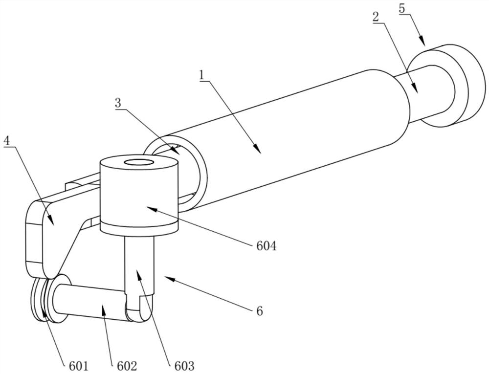
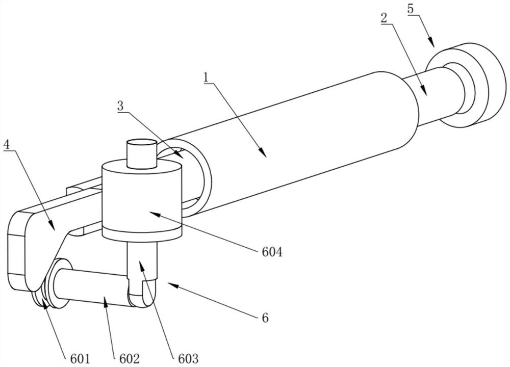
[0038] Such as Figure 1-3 As shown, an interlock mechanism includes an interlock driving member 1, a first driving rod 2 protrudes from one end of the interlocking driving member 1, and a second driving rod 3 protrudes from the other end, and the first driving rod 2 It moves synchronously with the second driving rod 3, the end of the first driving rod 2 is provided with a first locking mechanism 5, the end of the second driving rod 3 is connected with a driving plate 4, and the driving plate 4 is connected with a second locking mechanism. Agency 6;

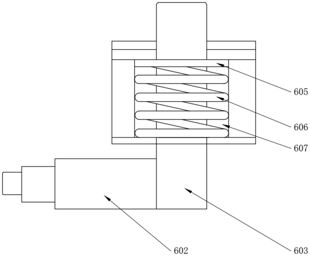
[0039]The second locking mechanism 6 includes a pulley 601 matched with the driving plate 4, the pulley 601 is rollingly connected with the driving plate 4, the pulley 601 is rotatably connected to one end of the dial shaft 602, and the other end of the dial shaft 602 is connected with a locking pin 603, the locking end of the locking pin 603 penetrates and protrudes from the top of the fixed body 604, the locking pin 603 is sli...

Embodiment 2

[0054] Such as Figure 4 As shown, the difference between the present embodiment and the first embodiment is that there are at least two second locking mechanisms 6, the locking directions of the plurality of second locking mechanisms 6 are different, and the plurality of second locking mechanisms 6 They are all connected to the drive plate 4, and the drive plate 4 is provided with variable cross-section steps that match each second locking mechanism 6. Through the drive of the interlock drive 1, mechanical interlock in multiple different directions can be realized. The structure Reasonable, improving the convenience of use.


PUM


Abstract

The invention belongs to the technical field of locking, and provides an interlock mechanism. A first drive rod is protruded from one end of the interlock drive member, a second drive rod is protruded from the other end, and a second drive rod is provided on the end of the first drive rod. There is a first locking mechanism, the end of the second driving rod is connected to a driving plate, and the second locking mechanism is connected to the driving plate; the second locking mechanism includes a pulley matched with the driving plate, and the pulley is rotatably connected to the dial shaft One end of the dial shaft, the other end of the dial shaft is connected with a locking pin, the locking end of the locking pin penetrates and protrudes from the top of the fixed body, the locking pin is slidingly connected with the fixed body, and the locking pin is provided with a fixed The limit block matched with the body, the return piece is connected between the limit block and the fixed body, and the return piece is arranged on the side of the limit block close to the dial shaft. The present invention can realize interlocking in two directions or more than two directions through the driving of one interlocking driving part, and has simple structure and convenient operation and use.

Description

technical field [0001] The invention relates to the technical field of locking, in particular to an interlocking mechanism. Background technique [0002] At present, locking mechanisms are required in many mechanical mechanisms, especially in more complex mechanical structures. In order to facilitate operation and improve the convenience of use, it is often necessary to use interlocking mechanisms to achieve locking or locking of certain parts. unlock. [0003] However, there are still some problems in the current interlocking mechanism in use, such as: the interlocking in two directions or more than two directions cannot be easily realized, the structure is not reasonable enough, and the versatility and practicability of the structure are poor. Contents of the invention [0004] Aiming at the defects in the prior art, the present invention provides an interlocking mechanism to achieve the technical effect of interlocking in two or more directions. [0005] To achieve th...

Claims


Application Information

Patent Timeline
Patent Type & Authority Patents(China)
IPC IPC(8): B65G1/04
CPCF16B1/00
Inventor 周振坤郑华郑昇
Owner 湖南铭狮机械有限公司
Learn More