Cloaking method based on difference beam forming

A hidden sound and beam technology, applied in the field of hidden sound based on differential beamforming, can solve the problems of poor dynamic effect, unsatisfactory communication headset promotion, unable to meet the application of hidden sound, etc., and achieve the effect of good hidden sound effect.

Inactive Publication Date: 2018-07-27
临境声学科技江苏有限公司
View PDF4 Cites 1 Cited by
  • Summary
  • Abstract
  • Description
  • Claims
  • Application Information

AI Technical Summary

Problems solved by technology

Although bone conduction microphone technology has made a breakthrough, the current promotion of its communication earphones is not very ideal. There are several problems: 1) poor dynamic effect; 2) high cost; 3) poor packaging effect; 4) poor sound quality
However, the separation performance achieved by the current separation technology is still very limited, which cannot meet the needs of hidden sound applications.

Method used


Image

  • Cloaking method based on difference beam forming
  • Cloaking method based on difference beam forming
  • Cloaking method based on difference beam forming

Examples


Embodiment Construction

[0064] The technical solutions of the present invention will be clearly and completely described below through specific embodiments.

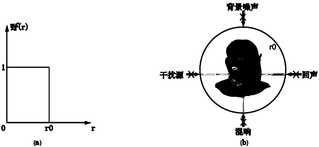
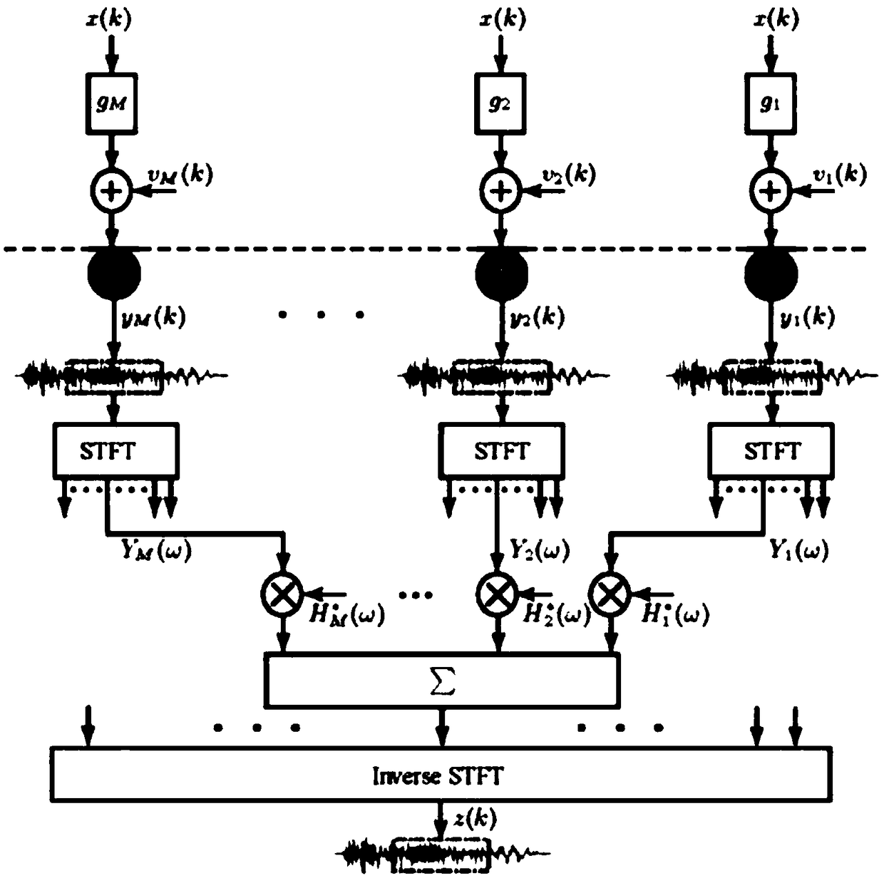
[0065] The hidden sound method based on the differential beamforming of the present invention, the method is to first use the short-time Fourier transform to decompose the time domain signal received by the sensor array into sub-band signals, and construct an appropriate hidden sound filter on each sub-band , so that the acoustic signal from the sound source within the hidden sound distance passes through the hidden sound filter without attenuation, and finally the estimated signal is obtained by inverse STFT.

[0066] Method of the present invention comprises the steps:

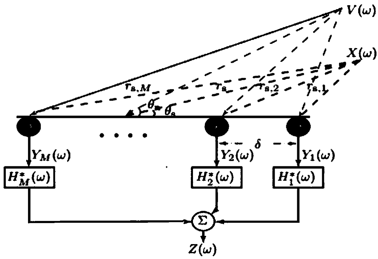
[0067] S1: According to the structure of the array, the number of array elements, the position of the sound source and other parameters, construct the steering vector

[0068]

[0069] S2: The signal y received by the sensor in the microphone array m (k)=x m (k)+v m (k...


PUM


Abstract

The invention discloses a cloaking method based on difference beam forming. According to the method, by means of short time Fourier transform, a time-domain signal received by a sensor array is decomposed into frequency-domain sub-band signals, cloaking filters based on N-order difference beam forming are constructed on various sub-bands, therefore, a sound signal from a sound source within the cloaking distance passes through the cloaking filters in an unattenuated mode, and finally an estimated signal is obtained through inverted STFT. The cloaking method has the good cloaking effect.

Description

technical field [0001] The present invention relates to a sound hiding technology based on a microphone array, in particular to a sound hiding method based on differential beam forming. Background technique [0002] The research on hidden sound technology has a long history. People have mainly explored two methods in the field of acoustic signal sensing: bone conduction microphone and ultrasonic microphone, and explored signal separation technology and differential microphone array in the field of acoustic signal processing. [0003] Bone conduction microphones use the slight vibration of the head and neck bones caused by human speech to collect sound signals and convert them into electrical signals. Because it is different from traditional microphones that pick up sound through air conduction, it can also transmit high-definition sound in a very noisy environment. As early as hundreds of years ago, people had many practical applications of bone conduction technology, but t...

Claims


Application Information

Patent Timeline
Patent Type & Authority Applications(China)
IPC IPC(8): H04R3/00
CPCH04R3/00H04R2430/00
Inventor 陈景东梁菲菲王雪瀚黄海聂玮奇
Owner 临境声学科技江苏有限公司
Why Eureka
Try Eureka