Virtual image distance measuring system and virtual image distance measuring determining method

A measurement system and image distance technology, applied in the virtual field, can solve problems such as high equipment requirements

Active Publication Date: 2018-08-03
BOE TECH GRP CO LTD +1
View PDF5 Cites 7 Cited by
  • Summary
  • Abstract
  • Description
  • Claims
  • Application Information

AI Technical Summary

Problems solved by technology

[0004] The invention provides a virtual image distance measuring system and a method for determining the virtual ima

Method used


Image

  • Virtual image distance measuring system and virtual image distance measuring determining method
  • Virtual image distance measuring system and virtual image distance measuring determining method
  • Virtual image distance measuring system and virtual image distance measuring determining method

Examples


Embodiment 1

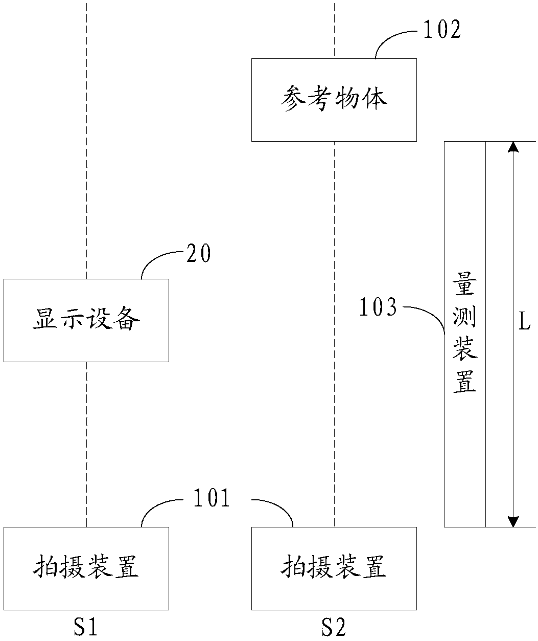
[0037] refer to figure 1 , shows a schematic structural diagram of a virtual image distance measuring system provided by an embodiment of the present invention. The virtual image distance measuring system is used to measure the virtual image distance of the virtual object displayed on the display device 20, and the system includes a shooting device 101, a reference object 102 and a measuring device 103;

[0038] The shooting device 101 has a first shooting position S1 and a second shooting position S2, in the first shooting position S1, the display device 20 is located on the optical axis of the shooting device 101; in the second shooting position S2, the reference object 102 is located on the optical axis of the photographing device 101;

[0039] The shooting device 101 is configured to focus on the virtual object in a preset mode when in the first shooting position S1, so that the virtual object can be clearly imaged in the shooting device 101;

[0040] The reference objec...

Embodiment 2

[0057] refer to Figure 4 , shows a flowchart of steps of a method for determining the image distance of a virtual image provided by an embodiment of the present invention. Applied to the virtual image image distance measuring system as described in Embodiment 1, the method includes:

[0058] Step 301 , when the shooting device 101 is in the first shooting position S1 , focus on the virtual object displayed on the display device 20 in a preset mode, so that the virtual object is clearly imaged in the shooting device 101 .

[0059] In this embodiment, the display device 20 displays a virtual object, and when the shooting device 101 is at the first shooting position S1, the display device 20 is located on the optical axis of the shooting device 101, and the shooting device 101 focuses on the virtual object in a preset mode, and the virtual Objects are clearly imaged in the camera 101 .

[0060] Optionally, the shooting parameters of the shooting device 101 in the preset mode a...


PUM


Abstract

The invention provides a virtual image distance measuring system and a virtual image distance measuring determining method. The system includes a photographing device, a reference object, and a measuring device. The photographing device is configured to focus a virtual object in a preset mode when being at a first photographing position so that the virtual object is clearly imaged in the photographing device. The reference object is configured, when the photographing device is in a second photographing position and in a focusing state, to move along the optical axis until clearly imaged in thephotographing device. The measuring device is configured to calibrate the distance between the reference object and the photographing device when the reference object is clearly imaged in the photographing device, wherein the distance is the virtual image distance of the virtual object. The method for determining the virtual image distance is simple and easy to operate, and can meet the detectionand correction requirements of display devices such as a virtual reality device and an augmented reality device, and solves a problem that equipment is highly required for determining the virtual image distance in the prior art.

Description

technical field [0001] The invention relates to the field of virtual technology, in particular to a virtual image image distance measuring system and a method for determining the virtual image image distance. Background technique [0002] Images formed by display devices such as virtual reality (Virtual Reality, VR) and augmented reality (Augmented Reality, AR) are all virtual images, and the measurement of the image distance of the virtual images is very important. Because the virtual image distance directly affects the effect of anti-distortion and spatial position depth, it is visually closest to the consumer experience of the display device. If the virtual image distance is not correct, it will directly affect the matching of software and hardware parameters and the final effect of the display device. [0003] At present, there are mainly the following ways to determine the image distance of the virtual image: 1. Obtain the image distance of the virtual image according ...

Claims


Application Information

Patent Timeline
IPC IPC(8): G01M11/02
CPCG01M11/00
Inventor 张浩刘亚丽陈丽莉王晨如董瑞君张雪冰陈寅伟王雪丰孙玉坤苗京花
Owner BOE TECH GRP CO LTD
Why Eureka
Try Eureka