a forming mold

A technology for forming molds and concave molds, applied in the direction of forming tools, manufacturing tools, metal processing equipment, etc., can solve the problems of improving and reducing production efficiency, multiple production steps, etc., and achieve the effect of reducing costs and reducing the use of molds

Active Publication Date: 2019-06-04
ANHUI JIANGHUAI AUTOMOBILE GRP CORP LTD
View PDF5 Cites 0 Cited by
  • Summary
  • Abstract
  • Description
  • Claims
  • Application Information

AI Technical Summary

Problems solved by technology

The above method needs to add a pair of shaping molds; adding molds not only increases the production cost, but also reduces the production efficiency due to the extra production steps

Method used


Image

  • a forming mold
  • a forming mold
  • a forming mold

Examples


Embodiment Construction

[0028] The embodiments described below by referring to the figures are exemplary only for explaining the present invention and should not be construed as limiting the present invention.

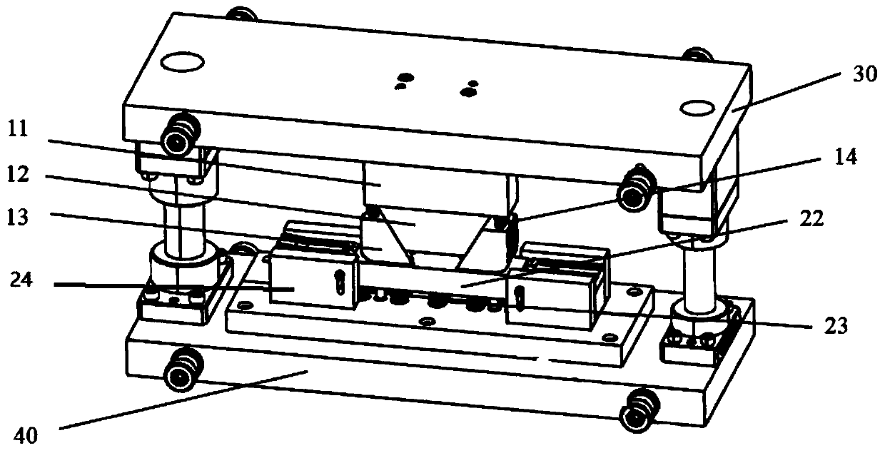
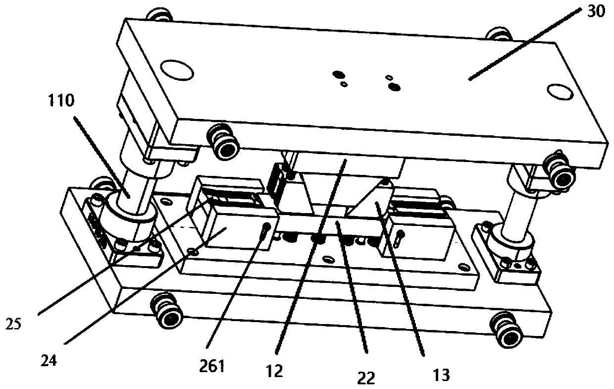
[0029] Embodiments of the present invention: as figure 1 and 2 As shown, a molding die is provided, including an upper mold base 30, two die holders 24, a die 22, a punch fixing plate 11, a punch 12 and a driving wedge 13, and the upper mold base 30 is Under the action of the push mechanism, the guide column 110 moves closer to or away from the lower die base 40; the two die holders 24 are fixed on the lower die base 40 at a certain distance; the two ends of the die 22 They are respectively slidably connected with the respective corresponding die fixing parts 24; the die 22 can move up and down. The two ends of described die 22 are all connected to respectively corresponding reversing die 25 by connector 263, and described reversing die 25 is placed on reversing die support member 242; Die...


PUM


Abstract

The invention discloses a forming die which comprises an upper die holder, two cavity die retainers, a cavity die, a terrace die and two drive tapered wedges. The upper die holder moves to be close toor away from a lower die holder along guide pillars under action of a pushing mechanism; the two cavity die retainers are fixed on the lower die holder by a certain distance; two ends of the cavity die are in slide connection with the corresponding cavity die retainers respectively; two ends of the cavity die are connected to corresponding turnover cavity dies through connectors; the terrace diedrives the cavity die to slide downwards along the cavity die retainers under driving of the upper die holder; the two drive tapered wedges slide obliquely along corresponding side surfaces of the terrace die. Compared with the prior art, the drive tapered wedges and the terrace die are in relative sliding so that adjustment of width of the terrace die is achieved, and further, processing of negative angles of stamping parts can be realized by cooperation of the turnover cavity dies; processing can be completed by one die only, and usage of the die is reduced and cost is lowered as compared with the prior art.

Description

technical field [0001] The invention relates to a fixture, in particular to a molding die used for processing straight arm pin holes. Background technique [0002] At present, according to product design requirements, in auto parts, there are many parts that inevitably have negative angles in the flanging. The problem of negative angles is a difficult point in making molds, which brings difficulties to the process; If there is a negative angle, the process is more difficult to achieve. The main reason is that due to the negative angle of the part flanging, when the mold is returning the material, it is easy for the part to get stuck on the mold and cannot be taken out. In the prior art, in the stamping process, the bending process requiring a negative angle is generally completed in three stations. Adopting the above method needs to add a pair of shaping molds; increasing the mold not only causes the improvement of production cost, but also reduces the production efficienc...

Claims


Application Information

Patent Timeline
Patent Type & Authority Patents(China)
IPC IPC(8): B21D37/10B21D45/04
CPCB21D37/10B21D45/04
Inventor 李燕王三星王双枝杨谊丽孔凡燕孙连福崔礼春杜长胜
Owner ANHUI JIANGHUAI AUTOMOBILE GRP CORP LTD
Why Eureka
Try Eureka