Leather belt buckle

A belt buckle and belt body technology, applied in the direction of belt buckles, fasteners, clothing, etc., can solve the problems of easy damage to the belt body, fastening, loosening, and troublesome adjustment of the tightness, and the process of adjusting the tightness is simple. Effect

Pending Publication Date: 2018-08-14
赵春禹
View PDF0 Cites 1 Cited by
  • Summary
  • Abstract
  • Description
  • Claims
  • Application Information

AI Technical Summary

Problems solved by technology

[0004] The invention provides a belt buckle, which aims to solve the problem that the existing pin buckle belt buckle is fastened, loosened, and the process of adjusting the tightness is cumbersome, and the belt body is easy to be damaged

Method used


Image

  • Leather belt buckle
  • Leather belt buckle
  • Leather belt buckle

Examples


Embodiment 1

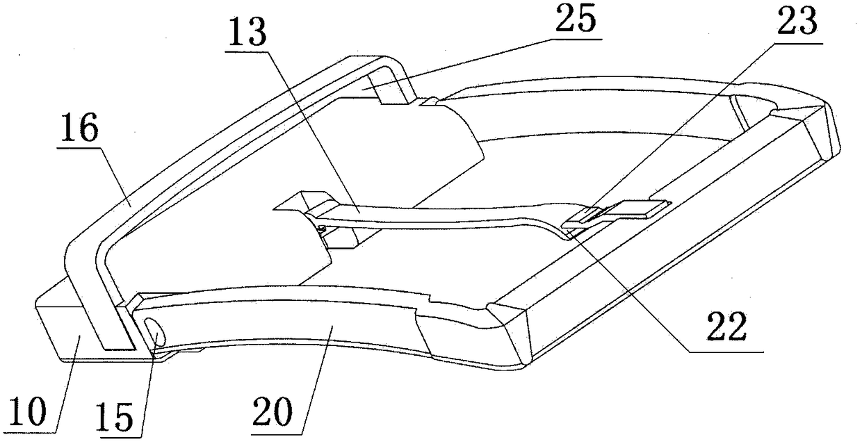
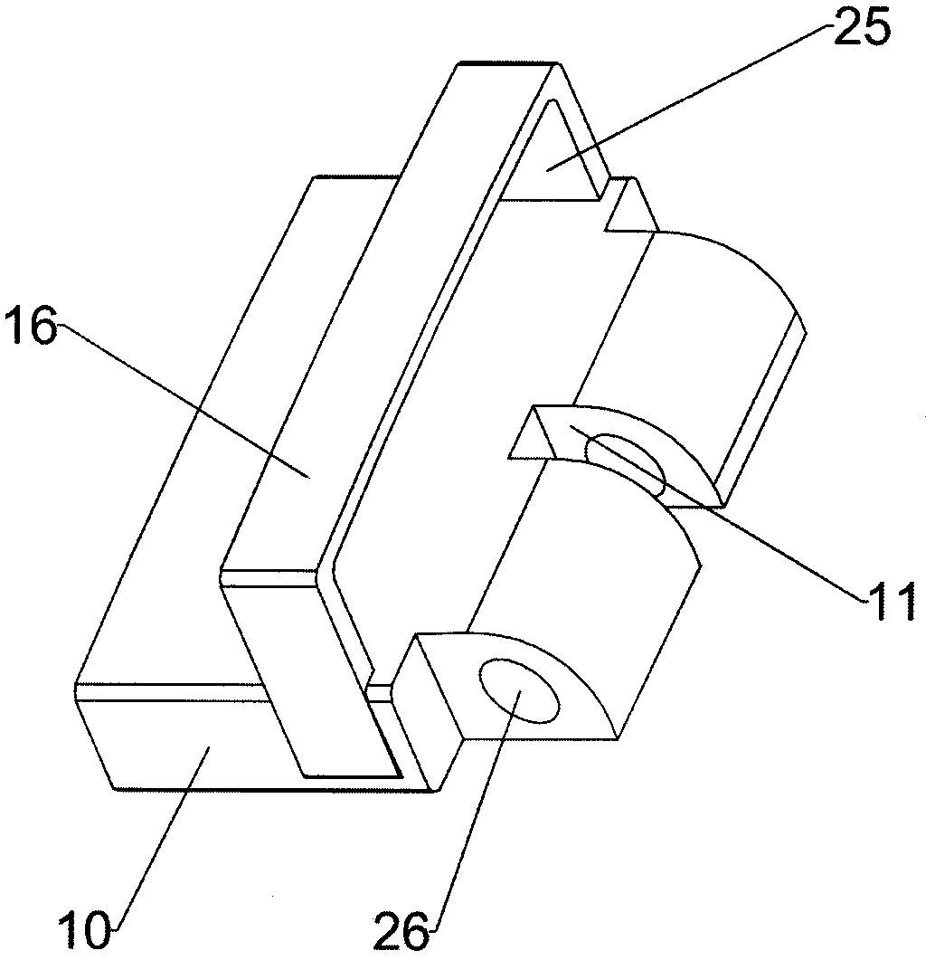
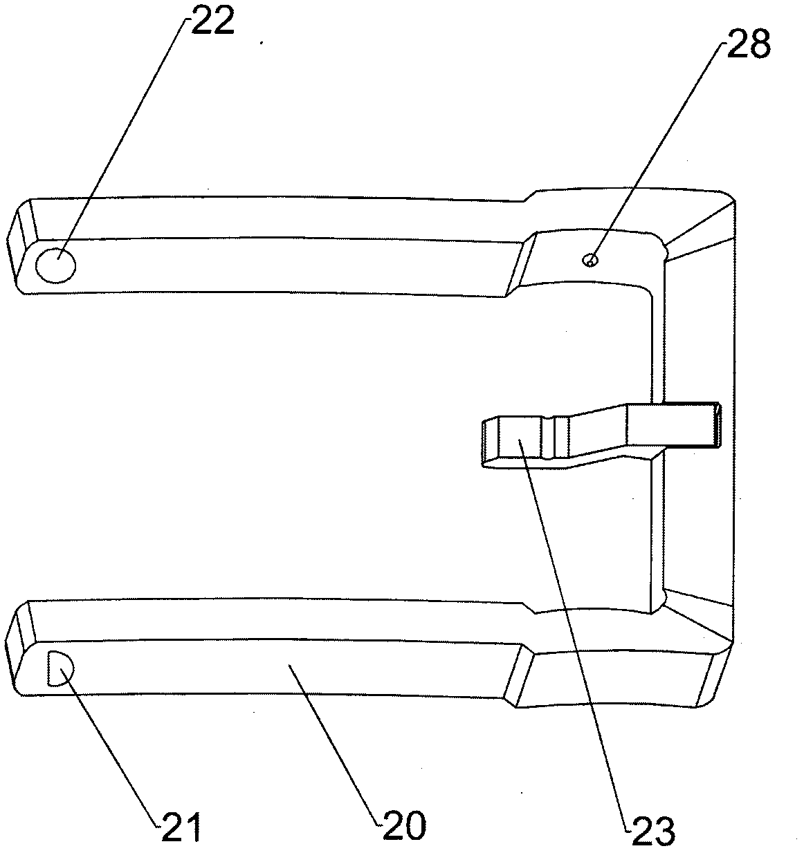
[0041] refer to Figure 1 to Figure 5 , a belt buckle, comprising a body 10, a plate control body 20, a guide needle 13 for guiding the insertion of the belt body, and a limit needle 23 for limiting the position of the belt body; the rear end of the body 10 is provided with a belt clamping portion, and The front end of the main body 10 is connected with a rotating shaft 15 arranged in the left and right directions; the inner surface of the front end of the board control body 20 is provided with a limit pin 23, and the rear end of the board control body 20 is fixedly connected with the rotating shaft 15; the outer surface of the front end of the body 10 is provided with a concave Groove 11, the guide pin 13 is located in the groove 11, the rear end of the guide pin 13 is connected to the rotating shaft 15, the front end of the guide pin 13 is located below the limit pin 23; the rear end of the guide pin 13 is connected with the return spring 12 and the rotating shaft The body 1...

Embodiment 2

[0058] refer to Figure 12 Figure 13 The difference from Embodiment 1 lies in the difference in the structure of the guide needle. In this embodiment, the rotating part 131 of the guide needle 13 can be rotatably connected or fixedly connected. The guide needle 13 can also be a detachable structure. The two connection ends are respectively provided with corresponding grooves and protrusions, and are provided with a first connection hole 136 of the split end, and a second connection hole 137 of the split end, and are connected by the split end rotating shaft 138 and the split end reset spring. 139 connection, the split end rotating shaft 138 diameter is the same as the first connecting hole 136 of the split end and the second connecting hole 137 of the split end, and can freely rotate and reset.

Embodiment 3

[0060] refer to Figure 14 Figure 15 The difference from Embodiment 1 is that a conversion panel 50 is added above the main body of the belt buckle, which is a square sheet structure. The left and right sides of the conversion panel 50 are respectively provided with conversion plug connectors, the left side is the first plug connector 51, and the right side The side is the second plug connector 52, which is respectively provided with a first concave point 53 and a second concave point 54, and is used in conjunction with the first convex point 27 and the second convex point 28 on the left and right sides of the board control body 20, so that the The conversion panel 50 is fixed on the panel control body 20 and can also be easily removed.

[0061] refer to Figure 16 Figure 17 , the difference from Embodiment 1 is that the main body 10 is two cylindrical structures with through holes.


PUM


Abstract

The invention provides a leather belt buckle, which solves the problem that the process of the prior needle-buckled belt buckle of buckling and looseness, and the tightness process is troublesome andthe belt body is easy to be damaged. The belt buckle comprises a body, a plate control body and a guide pin used for guiding the belt body to penetrate and limit pin limiting the position of the beltbody; the rear end of the body is provided with a belt body clamping part, and the front end of the body is connected with a rotating shaft which is arranged in a left-right direction; the outer surface of the inner side of the front end of the plate control body is provided with a limiting needle, and the rear end of the plate control body is fixedly connected with the rotating shaft; the outer surface of the front end of the body is provided with a groove, the guide pin is positioned in the groove, the rear end of the guide pin is connected to the rotating shaft, and the front end of the guide pin is positioned below the limiting needle; a return spring is connected with the rotating shaft at the rear end of the guide pin; the body, the plate control body, the guide pin and the limitingneedle form a belt body penetrating guide hole which is opened in the front-back direction; the outer surface of the outer body is provided with a limiting frame, and a belt body penetrating hole which is opened in the front-back direction is formed between the limiting frame and the outer surface of the outer body. The leather belt buckle has the advantages of fastening, loosening, adjusting andsimpleness and flexibility.

Description

technical field [0001] The invention relates to a belt buckle. Background technique [0002] At present, the working principle of the pin-type belt buckle on the market is as follows; when fastening, one hand needs to hold the left and right sides of the belt buckle's plate control body, and the other hand passes the free end of the belt body through the plate control body, and The front end of the plate control body is bent, and the front end of the limit pin is lifted upwards. When the belt body is worn to the desired position, pass the limit pin through the limit hole of the belt body, and then insert the free end of the belt body above the limit pin. Pass through the limiter. When loosening, hold the left and right sides of the control body of the belt buckle with one hand, pull the free end of the belt away from the insertion hole with the other hand, and bend it toward the front end of the control body. Take advantage of the trend to get out of the limit pin, and at ...

Claims


Application Information

Patent Timeline
Patent Type & Authority Applications(China)
IPC IPC(8): A44B11/24
CPCA44B11/24
Inventor 赵春禹
Owner 赵春禹
Why Eureka
Try Eureka