Simple blast hole plugging device for bench blasting and application method of simple blast hole plugging device

A plugging device and step blasting technology, which is applied in blasting and other directions, can solve the problems of explosive energy waste, shot blasting, and explosive rejection of explosives, and achieve the effects of improving energy utilization, ensuring plugging quality, and prolonging action time.

Pending Publication Date: 2018-08-17
GUIZHOU HIGHWAY ENG GRP +1
View PDF0 Cites 3 Cited by
  • Summary
  • Abstract
  • Description
  • Claims
  • Application Information

AI Technical Summary

Problems solved by technology

Blast holes are generally vertical or vertically inclined holes. After the charging process is over, in order to ensure that the explosive energy of the explosives is used to break rocks as much as possible and prevent energy from leaking and wasting, the blast holes need to be blocked, and the length of the plugging is According to the design of the blasting site, if the blockage section is too long and too dense, it is easy to cause the explosive to fail to explode, and if the blockage end is not in place or the blockage is not dense, it will often lead to the phenomenon of "blasting", resulting in a waste of explosive energy
[0003] The difficulty of plugging vertical or vertically inclined blastholes is that due to the deadweight of the blasthole or plugging material, if the diameter of the blasthole or plugging material is small, it is easy to fall directly when it is filled into the blasthole. The diameter of the material is too large, and the friction with the orifice is large, making it difficult for the blasting mud and plugging material to enter the blast hole, and the designed length of the packing section cannot be reached

Method used


Image

  • Simple blast hole plugging device for bench blasting and application method of simple blast hole plugging device
  • Simple blast hole plugging device for bench blasting and application method of simple blast hole plugging device
  • Simple blast hole plugging device for bench blasting and application method of simple blast hole plugging device

Examples


Embodiment Construction

[0025] The present invention will be described in detail below in conjunction with the accompanying drawings and embodiments, and the content of the present invention is not limited to the following embodiments.

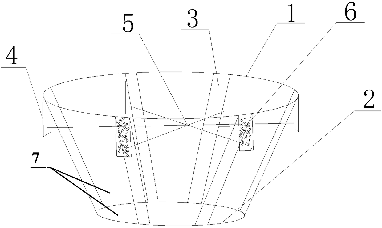
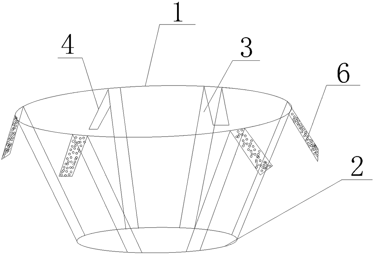
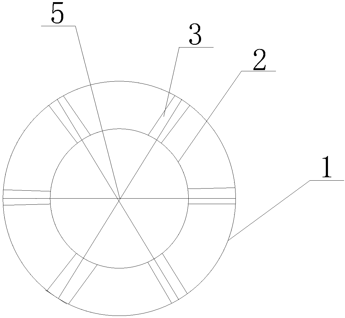
[0026] see Figure 1 to Figure 5 , a simple plugging device for step blasting, mainly composed of a large ring 1, a small ring 2, a connecting piece 3, a film 7, an elastic piece 4, a chisel 6, and a string 5, and is characterized in that: The large ring 1 and the small ring 2 are hinged by six connecting pieces 3, and the six connecting pieces 3 are symmetrically distributed on the ring, and the film 7 covers the small ring 2 to the large ring 1 and is fixed on the large ring. On the ring 1, one end of the six elastic pieces 4 is fixed on the big ring 1, at the same position as the connecting piece 3, and has a certain angle with the big ring 1, and the other end is a free end, and the six The diameter of the circle formed by the free ends of the elastic sheet 4 is...


PUM


Abstract

The invention relates to the technical field of blast hole plugging for bench blasting and particularly relates to a simple blast hole plugging device for bench blasting. The simple blast hole plugging device is characterized in that one end of each of six elastic plates is fixed to a large circular ring; the diameter of a circle defined by the other free ends of the six elastic plates is larger than the diameter of the large circular ring; a string is tensioned to make the elastic plates be in a pressed state, and at the moment the diameter of the circle defined by the free ends of the elastic plates is the same as the diameter of the large circular ring; when a lifting hook rod with scales is used for hooking the string so that the string can be put at a designed plugging position of a blast hole, the string is cut off to release the free ends of the pressed elastic plates; chiseling nails attached to elastic plates make close contact with the wall of the blast hole; and subsequentlystemming is put into the blast hole to implement the plugging. The simple blast hole plugging device provided by the invention is simple in structure and convenient to use, solves the difficulty of blocking of a vertical blast hole, can precisely meet the designed length of a plugging section of the blast hole, guarantees the plugging quality of the blast hole, improves the energy utilization rate of explosives and improves the blasting effect.

Description

technical field [0001] The invention relates to the technical field of blasting charge plugging, in particular to a simple blast hole plugging device for step blasting and a method for using the same. Background technique [0002] With the advancement of drilling machinery and the improvement of the ability of excavating machinery to excavate earth and rocks, step blasting has moved forward to deep hole smooth blasting. Blast holes are generally vertical or vertically inclined holes. After the charging process is over, in order to ensure that the explosive energy of the explosives is used to break rocks as much as possible and prevent energy from leaking and wasting, the blast holes need to be blocked, and the length of the plugging is According to the design of the blasting site, if the plugging section is too long and too dense, it is easy to cause the explosive to fail to explode, and if the plugging end is not in place or the plugging is not dense, it will often lead to ...

Claims


Application Information

Patent Timeline
Patent Type & Authority Applications(China)
IPC IPC(8): F42D1/08
CPCF42D1/08
Inventor 陈雪峰赵孝学马浪张龙刘江华梁红兵汪海波
Owner GUIZHOU HIGHWAY ENG GRP
Why Eureka
Try Eureka