Improved bridge facility

An improved, bridge technology, applied in mechanical equipment, photovoltaic power generation, photovoltaic modules, etc., can solve the problems of monitoring dead corners, waste of mains power, difficulty in adjusting the angle of monitoring devices, etc., to prolong the service life, increase the monitoring range, and have a simple structure. Effect

Inactive Publication Date: 2018-08-17
广州上龙智能科技有限公司
View PDF5 Cites 0 Cited by
  • Summary
  • Abstract
  • Description
  • Claims
  • Application Information

AI Technical Summary

Problems solved by technology

[0002] Monitoring devices are installed on some bridges to monitor the passing vehicles to increase the safety of bridge traffic. However, traditional bridge monitoring devices have difficulty adjusting the angle, and there are dead spots in the monitoring. At the same time, they need to be connected to the mains, which greatly causes the waste of electricity

Method used


Image

  • Improved bridge facility
  • Improved bridge facility
  • Improved bridge facility

Examples


Embodiment Construction

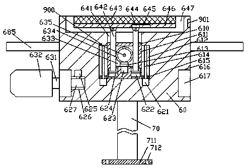
[0015] Such as Figure 1-Figure 3 As shown, an improved bridge facility of the present invention includes a frame 60 and a monitoring probe 632 cooperatingly installed on the frame 60, and a circular shroud 685 is annularly arranged on the outer circumference of the frame 60, thereby It can prevent rainwater from entering the monitoring probe 632 and causing damage. The top end surface of the frame 60 is provided with an installation cavity 647, and the inner wall of the frame 60 on the lower side of the installation cavity 647 is connected with a first A chute 641, the first chute 641 is movably fitted with a sliding table 611, the left and right sides of the sliding table 611 are provided with a push structure and a touch structure, and the inner wall of the sliding table 611 is provided with a first rotary warehouse 633, the first rotating column 635 extending forward and backward in the first rotating housing 633 is connected with the front and rear inner walls of the firs...


PUM


Abstract

The invention discloses an improved bridge facility which comprises a rack and a monitoring probe arranged on the rack in a matched mode. A circular shielding plate is annularly arranged on the outercircumference of the rack, and a mounting cavity is formed in the end surface of the top of the rack, and a first sliding chute is formed in the inner wall body of the rack at the lower side of the mounting cavity in a communicative way. A sliding table is movably matched with the first sliding chute in a matched mode, and pushing structures are arranged on the left side and the right side of thesliding table, and a first rotating bin is arranged in the inner wall body of the sliding table, and a first rotating column which is in rotating fit connection with the front inner wall and the rearinner wall of the first rotating bin is arranged in the first rotating bin in a horizontal extending manner. A first bevel wheel is fixedly arranged on the outer surface of the first rotating column in a circumferential direction, and a second bevel wheel in matched connection with the first bevel wheel is arranged on the inner bottom wall of the first rotating bin, and the bottom end face of thesecond bevel wheel is in power fit connection with a first motor.

Description

technical field [0001] The invention relates to the field of bridges, in particular to an improved bridge facility. Background technique [0002] Monitoring devices are installed on some bridges to monitor the passing vehicles to increase the safety of bridge traffic. However, traditional bridge monitoring devices have difficulty adjusting the angle, and there are dead spots in the monitoring. At the same time, they need to be connected to the mains, which greatly causes the Waste of electricity. Contents of the invention [0003] The technical problem to be solved by the present invention is to provide an improved bridge facility, which can solve the above-mentioned problems in the prior art. [0004] The present invention is achieved through the following technical solutions: An improved bridge facility of the present invention includes a frame and a monitoring probe cooperatingly installed on the frame, and a circular shield is arranged on the outer circumference of th...

Claims


Application Information

Patent Timeline
Patent Type & Authority Applications(China)
IPC IPC(8): H02S20/30F16M11/10
CPCF16M11/10H02S20/30Y02E10/50
Inventor 袁承宇
Owner 广州上龙智能科技有限公司
Why Eureka
Try Eureka