Unlock instant, AI-driven research and patent intelligence for your innovation.

Operation device

A technology for operating devices and operating switches, which can be used in emergency protection devices, instrument layout, transportation and packaging, etc., and can solve problems such as coordinate detection difficulties

Inactive Publication Date: 2018-08-21
KK TOKAI RIKA DENKI SEISAKUSHO
View PDF8 Cites 0 Cited by
  • Summary
  • Abstract
  • Description
  • Claims
  • Application Information

AI Technical Summary

Problems solved by technology

In particular, when the above-mentioned operation device is used in a vehicle, etc., since the installation area of ​​the display unit is limited, it is highly likely that it will be difficult to detect the approach of a finger or the like from around the display unit and to detect coordinates.

Method used


Image

  • Operation device
  • Operation device
  • Operation device

Examples


no. 1 approach

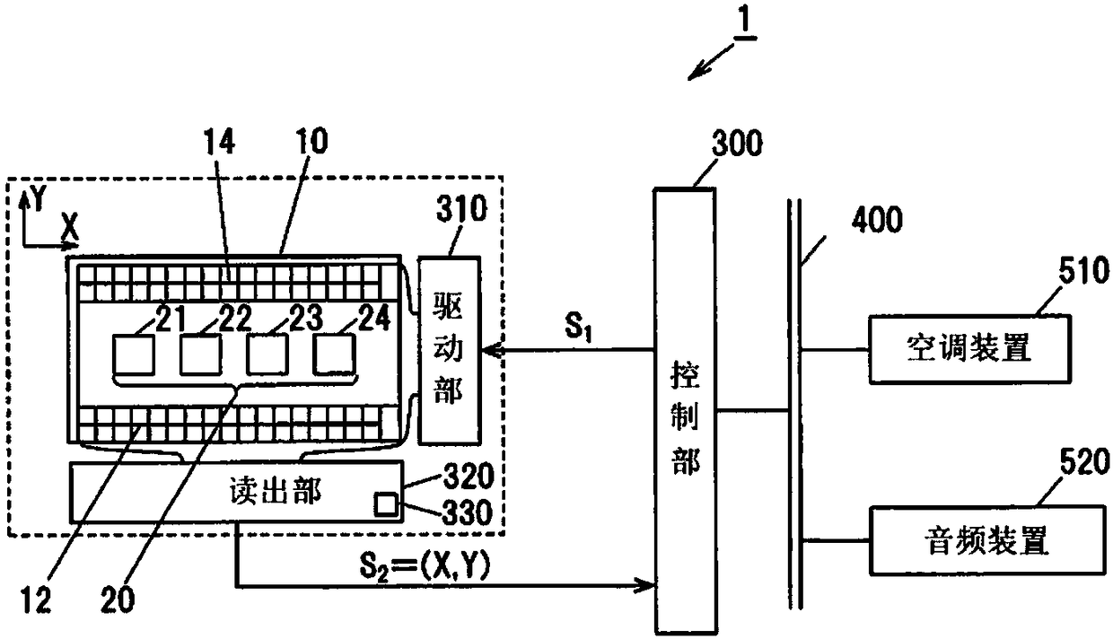
[0026] Figure 1A is a block diagram showing the configuration of the operating device according to the first embodiment of the present invention, Figure 1B It is a plan view showing the sensor panel of the operating device according to the first embodiment of the present invention. figure 2 It is an exploded perspective view showing the first detection electrode, the second detection electrode, and the insulating layer of the operation device according to the first embodiment of the present invention. in addition, Figure 3A is a plan view showing the wiring pattern of the first detection electrode, Figure 3B It is a plan view showing the wiring pattern of the second detection electrode.

[0027] (Structure of the operating device 1)

[0028] The operating device 1 of the invention of the present application has: a switch column 20 configured with a plurality of operating switches (21, 22, 23, 24); static detection sensors (first static detection sensor 12, second stati...

no. 2 approach

[0062] The second embodiment of the present invention is a configuration in which the control unit 300 determines which operation switch of the switch row the object to be detected has approached based on the temporal change of the two-dimensional coordinate value detected by the static electricity detection sensor.

[0063] Figure 6A It is a plan view showing the sensor panel of the operating device according to the second embodiment of the present invention, Figure 6B It is a plan view showing a state where an approaching finger moves to an operation switch.

[0064] The second embodiment detects the temporal change of the two-dimensional coordinate value detected by the static electricity detection sensor, and judges which operation switch is approached based on this. Various methods are considered for this determination method, but an example of the determination method is shown below.

[0065] (detection action)

[0066] The control unit 300 detects the count value o...

no. 3 approach

[0077] A third embodiment of the present invention is a structure in which switch columns are arranged in two layers.

[0078] Figure 7 It is a plan view showing the sensor panel of the operating device according to the third embodiment of the present invention. The upper switch row 20 ( 21 , 22 , 23 , 24 ) is, for example, an operating switch of a vehicle air conditioner, and the lower switch row 30 ( 31 , 32 , 33 , 34 ) is, for example, an operating switch of a vehicle audio device.

[0079] The first static electricity detection sensor 12 is arranged on the lower side of the two-layer switch rows 20 and 30 , and the second static electricity detection sensor 14 is arranged on the upper side. Similar to the first and second embodiments, the approach point P is detected based on the distribution of the count values ​​of the electrostatic capacitance values. Alternatively, the approach points P1 and P2 are detected at regular time intervals. Thereby, similar to the first e...


PUM


Abstract

The operation device 1 has: a switch array 20 in which operation switches (21, 22, 23, 24) are arranged; electrostatic detection sensors (first electrostatic detection sensor 12, first electrostatic detection sensor 14) which are disposed above or below the switch array 20, thereby detecting two-dimensional coordinate values when an object to be detected, such as a finger of an operator, has comeclose thereto; and a control unit 300 equipped with a determination part for determining whether or not the object to be detected has come close to any one of the operation switches of the switch array 20 on the basis of a detection result of the electrostatic detection sensors.

Description

technical field [0001] The invention relates to operating devices. Background technique [0002] A capacitive switch is proposed, comprising: a transparent electrode disposed on a light-transmitting protective cover covering a control object; and a detection circuit that detects changes in the capacitance of the transparent electrode to ground and outputs a detection signal to drive a control unit. As an operating device (instrument for a vehicle) having such an electrostatic capacitive switch, a device having the following components is known: a display unit for displaying vehicle operation information; a light-transmitting protective cover arranged in front of the display unit to protect the display unit; The capacitive switch includes a transparent electrode arranged at a position corresponding to the display part of the light-transmitting protective cover, and detects a change in the ground capacitance of the transparent electrode and outputs a detection signal; and a co...

Claims


Application Information

Patent Timeline
Patent Type & Authority Applications(China)
IPC IPC(8): G06F3/041B60R16/02G06F3/044H01H36/00
CPCH03K17/9622H03K2217/960725H01H2239/006G06F3/04186G06F3/0445G06F3/0446B60K35/10B60K2360/139B60K2360/141B60K2360/1446B60K35/60G06F3/044H03K17/962
Inventor 野口国俊
Owner KK TOKAI RIKA DENKI SEISAKUSHO