
Preparation method of electrode and membrane electrode for fuel cell with fully-ordered catalyst layer structure
A fuel cell electrode and ordered structure technology, applied in the direction of fuel cells, battery electrodes, structural parts, etc., to improve the performance of the monomer and the activity of the catalytic layer, improve the efficiency of electrochemical reactions and energy conversion, and reduce the resistance of material transfer Effect
- Summary
- Abstract
- Description
- Claims
- Application Information
AI Technical Summary
Problems solved by technology
Method used
Image

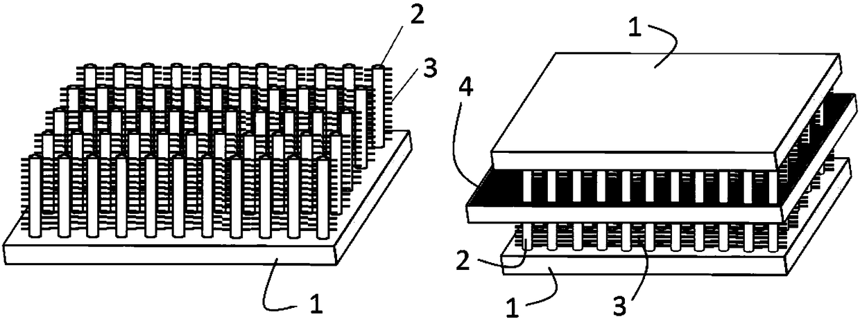
Examples
Embodiment 1
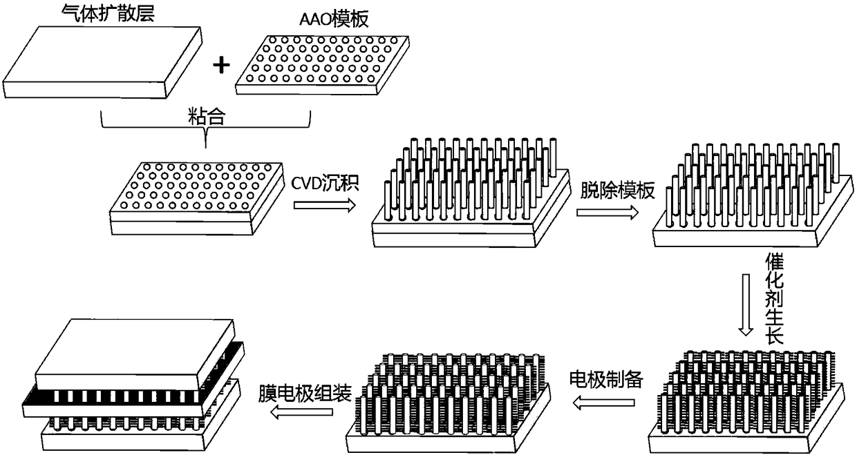
[0034] combined with figure 2 The process and process shown are used to prepare catalyst layer fully ordered polyelectrolyte membrane fuel cell electrodes and membrane electrodes, and conduct discharge tests. The main steps are as follows:
[0035] (1) In situ growth of VACNT arrays on the gas diffusion layer
[0036] After washing and drying a piece of AAO double-pass porous template with a size of 2.3cm×2.3cm (pore size is 30nm, thickness is 100μm), it is bonded with a piece of carbon paper of the same size as the gas diffusion layer 1, and placed in a tube furnace , pass through acetylene at 600°C for 60 minutes, and vapor-deposit it in the pores of the AAO template, and finally use 1mol / L NaOH solution to remove the AAO template to obtain carbon nanotubes 2 vertically grown on the gas diffusion layer 1 Arrays (VACNTs).
[0037] (2) In situ growth of Pt-NW
[0038] The gas diffusion layer loaded with the VACNT array prepared above was impregnated in 50ml with a concentr...
Embodiment 2
[0044] The catalyst layer fully ordered polyelectrolyte membrane fuel cell electrode and membrane electrode with N-doped VACNT array as the carrier were prepared according to the following steps, and the discharge test was carried out.
[0045] (1) In situ growth of N-doped VACNT arrays on the gas diffusion layer
[0046] After washing and drying a piece of AAO double-pass porous template with a size of 2.3cm×2.3cm (pore size is 30nm, thickness is 100μm), it is bonded with a piece of carbon paper of the same size as the gas diffusion layer 1, and placed in a tube furnace , pass through acetylene at 600°C for 60 min, make it vapor-deposit in the channels of the AAO template, and finally use 1mol / L NaOH solution to remove the AAO template, and obtain the carbon nanotube 2 array vertically grown on the gas diffusion layer 1 (VACNTs). Then, the gas diffusion electrode 1 grown with VACNT was placed in the tube furnace again, and NH was fed at a temperature of 500 °C 3 gas, the fl...
Embodiment 3
[0049] A fully ordered polyelectrolyte membrane fuel cell electrode and a membrane electrode with catalytic layer using S-doped VACNT array as a carrier were prepared according to the following steps, and the discharge test was carried out.
[0050] (1) In situ growth of S-doped VACNT arrays on the gas diffusion layer
[0051] Using the same method as in Example 1, VACNTs grown in situ on the gas diffusion layer 1 were firstly prepared. Then, the gas diffusion electrode grown with VACNT was placed in the tube furnace again, and H was introduced at 500 °C. 2 S gas, the flow rate is 0.1slpm, and the surface S-doped VACNT array is obtained
[0052] Step (2) in-situ growth of Pt-NW and step (3) membrane electrode assembly method are the same as in Example 1. Under the same conditions as in Example 1, the discharge test was carried out, and at a working voltage of 0.6V, the current density can reach 0.48A / cm 2 , the maximum power density reaches 0.82W / cm 2 .
PUM
| Property | Measurement | Unit |
|---|---|---|
| pore size | aaaaa | aaaaa |
| thickness | aaaaa | aaaaa |
| current density | aaaaa | aaaaa |
Abstract
Description
Claims
Application Information