Supercharge Your Innovation With Domain-Expert AI Agents!

Anti-vibration rubber bushing

A rubber bushing and anti-vibration technology, applied in the direction of high internal friction springs, etc., can solve the problems of limited installation space, limit of load resistance, inability to fully bear load reaction force, etc., and achieve reliable anti-vibration performance and excellent anti-vibration performance Effect

Inactive Publication Date: 2018-08-28
TOZEN CORP
View PDF1 Cites 0 Cited by
  • Summary
  • Abstract
  • Description
  • Claims
  • Application Information

AI Technical Summary

Problems solved by technology

Conventional rubber bushings support the reaction force of the joint only with urethane rubber as described above, but as the diameter of the joint increases, the reaction force increases, and the rubber cannot support it alone, and the rubber is completely crushed.
In addition, the installation space is also limited, and there is a limit to the load resistance
Therefore, there is a problem that even if it is used in a rubber flexible joint with a large diameter, it cannot sufficiently withstand a large load reaction force, and the deflection becomes large, so that the anti-vibration performance cannot be expected.
[0006] However, this anti-vibration rubber bush has a structure in which only the rubber elastic body is sandwiched between the inner cylinder fitting and the outer cylinder fitting as described above, so there is no major change from the conventional rubber bush described above, and there are the same The problem

Method used


Image

  • Anti-vibration rubber bushing
  • Anti-vibration rubber bushing
  • Anti-vibration rubber bushing

Examples


Embodiment Construction

[0042] Hereinafter, an embodiment of the present invention will be described with reference to the drawings.

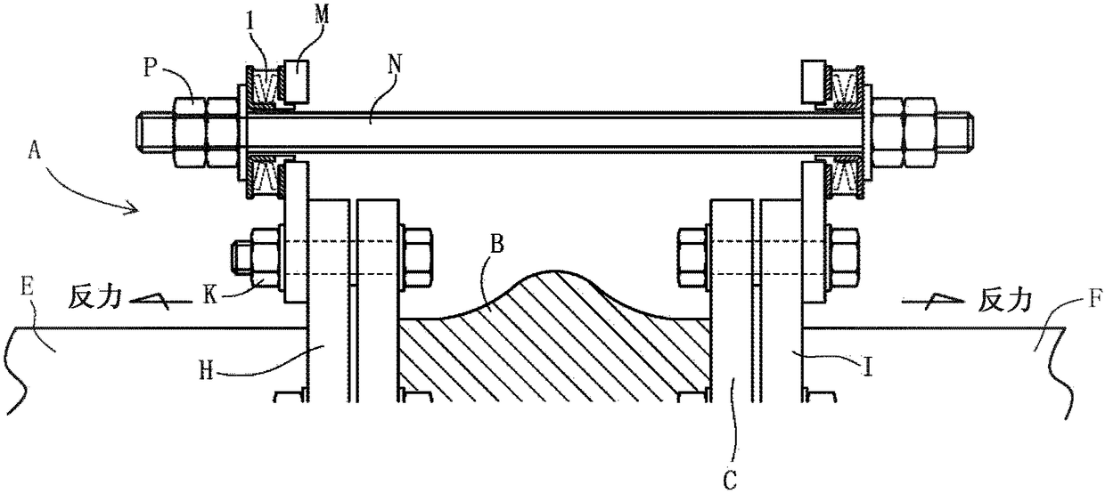
[0043] figure 1 It is a schematic diagram showing the use state (installation state) of the control unit that controls the elongation of the rubber flexible joint. In the figure, A is a flexible joint made of rubber, and the flexible joint A is composed of a cylindrical main body B made of rubber and metal flanges C attached to both ends of the main body. The flange part C abuts against the flange part H and I provided on the opposite ends of the pipes E and F respectively, and is fastened and fixed by bolts and nuts K. The above-mentioned pipes E and F are separated by a predetermined distance on both sides of the flange part C. Configured at intervals. During the above-mentioned fixing, the base end portion of the control unit board M is fixed to the outer surfaces of the flange portions H, I. Holes for control unit bolts are drilled at the front end of the contr...


PUM


Abstract

The invention provides an anti-vibration rubber bushing. Even though the anti-vibration rubber bushing is used for a large-diameter rubber flexible joint, the rubber bushing can bear relatively high load counter-force, and can obtain moderate flexure to exert anti-vibration performance. The anti-vibration rubber bushing (1) is provided with a first flange component (2) which is provided with a bolt through hole (6), a second flange component (3) which is provided with a bolt through hole (7) concentric to the bolt through hole of the first flange component, and an elastic rubber member (5) clamped between the first flange component and the second flange component. The elastic rubber member (5) is integrally configured with a spring member (8) which has better load-resisting property than the elastic rubber member, the spring member (8) being arranged in an embedded manner.

Description

technical field [0001] The present invention relates to an anti-vibration rubber bush, and more specifically, relates to a bolt mounted on a control unit for controlling the elongation of a rubber flexible joint to obtain load resistance (reaction force), moderate deflection, and anti-vibration performance. Excellent rubber bushing. Background technique [0002] Conventional rubber bushes of this type consist of urethane rubber and two steel plates (without welding), and are used in different sizes depending on the caliber of the rubber flexible joint and the type of reaction force. The thickness of the urethane rubber is about 10mm, and the hardness is 90Hs, which is harder than general synthetic rubber, and it is designed to withstand a large load. [0003] However, a control unit that controls the elongation of a rubber flexible joint generally requires a rubber bush as a vibration-proof member. Conventional rubber bushings support the reaction force of the joint only w...

Claims


Application Information

Patent Timeline
IPC IPC(8): F16F3/10
CPCF16F3/10
Inventor 室井仁志
Owner TOZEN CORP
Features
  • R&D
  • Intellectual Property
  • Life Sciences
  • Materials
  • Tech Scout
  • Unparalleled Data Quality
  • Higher Quality Content
  • 60% Fewer Hallucinations
Learn More