Motor cooling structure, power motor and electric drive system

A technology of motor cooling and liquid cooling structure, applied in electric components, cooling/ventilation devices, magnetic circuit shape/style/structure, etc., can solve the problems of rotor temperature rise, impact on bearing life, bearing overtemperature, etc.

Active Publication Date: 2018-08-28
NIO ANHUI HLDG CO LTD
View PDF12 Cites 8 Cited by
  • Summary
  • Abstract
  • Description
  • Claims
  • Application Information

AI Technical Summary

Problems solved by technology

[0004] For induction motors, due to the induced current on the rotor, a large amount of heat is generated on the rotor, but usually the heat dissipation of the rotor is difficult, and the temperature rise of the rotor is high; at the same time, the speed of the power motor is usually very high, up to 15000rpm, Under the condition of high-speed operation, the loss of the bearing itself increases. Considering the heat conduction of the temperature rise of the rotor itself, the temperature of the bearing is too high, which is very easy to cause overheating of the bearing, which seriously affects the life of the bearing.

Method used


Image

  • Motor cooling structure, power motor and electric drive system
  • Motor cooling structure, power motor and electric drive system
  • Motor cooling structure, power motor and electric drive system

Examples


Embodiment Construction

[0025] Specific embodiments of the present invention will be described in detail below with reference to the accompanying drawings. In the drawings, the same reference numerals represent the same or corresponding technical features.

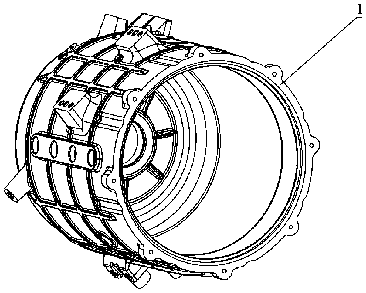
[0026] figure 1 It is a schematic cross-sectional view of an embodiment of the power motor according to the present invention. It can be seen from the figure that the power motor includes a motor casing 1, a stator winding 2, a stator core 3, a motor end cover 5, a rotor core 6, and the like.

[0027] In the figure, the stator winding 2 is embedded in the stator core 3, the stator core 3 is fitted on the motor casing 1 by shrink fitting, and the motor end cover 5 and the motor casing 1 are connected together by bolts. The motor casing 1 may have a built-in stator liquid cooling structure. When the motor is running, the coolant circulates in the stator liquid cooling structure to take away the heat from the motor stator. The cooling liquid her...


PUM


Abstract

The invention relates to a motor cooling structure, a power motor comprising same and an electric drive system. The motor cooling structure comprises a rotor liquid-cooling structure. The rotor liquid-cooling structure comprises a hollow blind hole in a rotor rotation shaft. The hollow blind hole is internally provided with a liquid-cooling pipeline. A first-end opening of the liquid-cooling pipeline extends to a blind end of the hollow blind hole, and a second-end opening of the liquid-cooling pipeline extends to an opening end of the hollow blind hole. The hollow blind hole and the liquid-cooling pipeline form a liquid-cooling flow path of the rotor liquid-cooling structure.

Description

technical field [0001] The invention relates to the technical field of power motors; specifically, the invention relates to a motor cooling structure, a power motor and an electric drive system. Background technique [0002] Taking electric vehicles as an example, their power motors strive to pursue high power / torque density, high efficiency, and high reliability. When designing, the selection of the electromagnetic load and thermal load of the motor tends to the limit, resulting in a significant increase in the loss and heat generation per unit volume, which has a significant impact on the power and torque density, efficiency, insulation material performance, life and reliability of the motor. Impact. [0003] To this end, it is necessary to improve the cooling and heat dissipation of the power motor, reasonably select and arrange the cooling system, avoid local hot spots, and try to fully discharge the heat in the motor. On the premise of ensuring the safe and reliable o...

Claims


Application Information

Patent Timeline
IPC IPC(8): H02K9/19H02K5/20
CPCH02K5/203H02K9/197H02K1/20
Inventor 张胜川兰红玉张诗香李鹏张敬才朱驾先许力文庄朝晖
Owner NIO ANHUI HLDG CO LTD
Why Eureka
Try Eureka