Control circuit and method for compensating output loss of power converter

A technology of power converters and control circuits, which is applied in the direction of converting DC power input to DC power output, control/regulation systems, and output power conversion devices, and can solve problems such as large output voltage errors and poor voltage stabilization effects

Active Publication Date: 2020-05-15
LEADTREND TECH
View PDF5 Cites 1 Cited by
  • Summary
  • Abstract
  • Description
  • Claims
  • Application Information

AI Technical Summary

Problems solved by technology

However, because the prior art also uses the compensation voltage VCOMP to determine the frequency reduction curve L corresponding to the gate control signal (such as figure 1 shown, and the gate control signal is used to control the power switch on the primary side of the power converter to turn on and off), and the compensation voltage VCOMP is in the frequency conversion intervals A and B of the frequency reduction curve L (such as figure 1 shown) does not change linearly and positively with the load coupled to the secondary side of the power converter, so the compensation corresponding to the output loss will also have nonlinear characteristics, resulting in the corresponding The error of the output voltage on the secondary side becomes larger
Therefore, the voltage stabilizing effect of the prior art is not good

Method used


Image

  • Control circuit and method for compensating output loss of power converter
  • Control circuit and method for compensating output loss of power converter
  • Control circuit and method for compensating output loss of power converter

Examples


Embodiment Construction

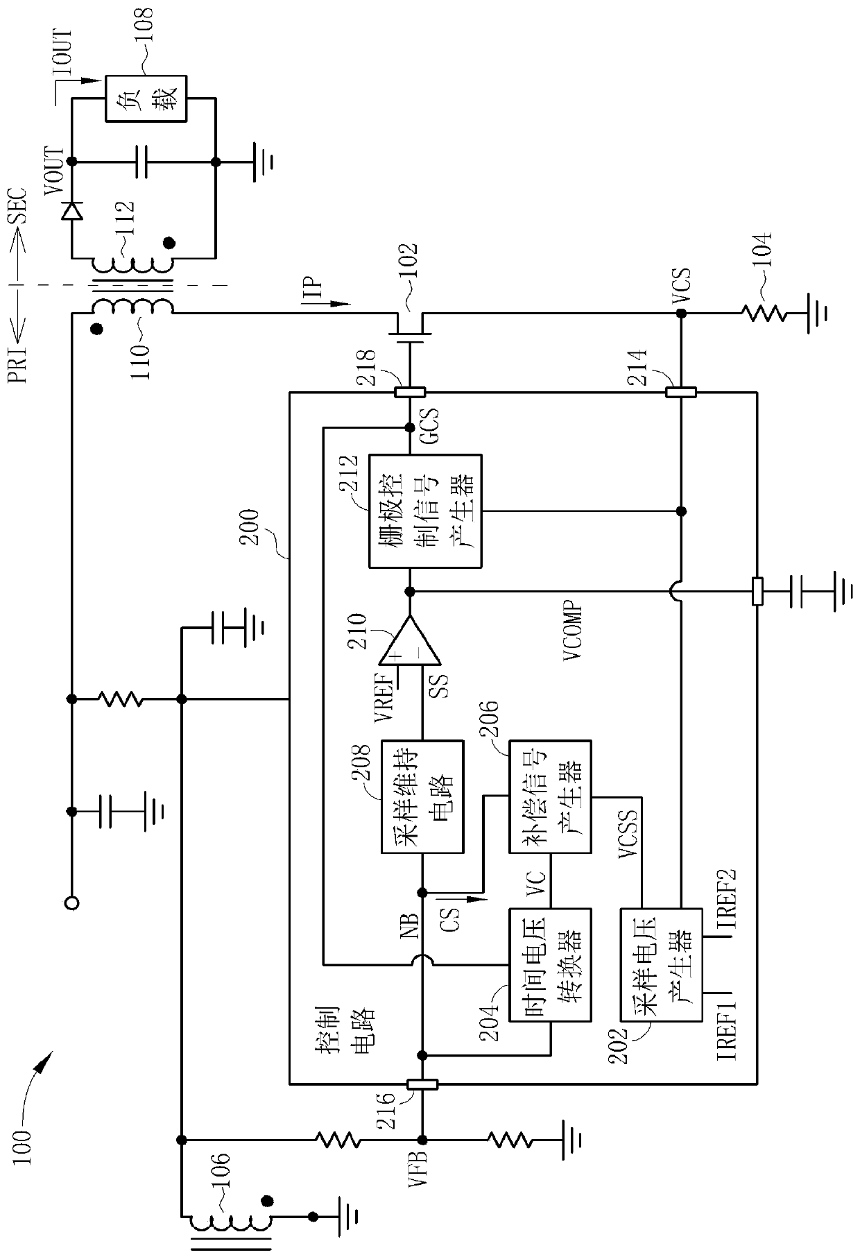
[0078]Please refer to figure 2 , figure 2 It is a schematic diagram of a control circuit 200 for compensating the output loss of the power converter 100 disclosed in the first embodiment of the present invention, wherein the power converter 100 is a flyback power converter. But the present invention is not limited to the fact that the power converter 100 is a flyback power converter. like figure 2 As shown, the control circuit 200 includes a sampling voltage generator 202 , a time-to-voltage converter 204 , a compensation signal generator 206 , a sample-and-hold circuit 208 , an error amplifier 210 and a gate control signal generator 212 . like figure 2 As shown, the sampling voltage generator 202 is used to generate a sampling voltage VCSS corresponding to the detection voltage VCS according to a first reference current IREF1, a second reference current IREF2 and a detection voltage VCS, wherein the sampling voltage generator 202 is controlled by The pin 214 of the ci...


PUM


Abstract

The invention discloses a control circuit and method for compensating the output loss of a power converter. The control circuit includes a sampling voltage generator, a time-to-voltage converter and a compensation signal generator. The sampling voltage generator generates a sampling voltage corresponding to the detection voltage according to a first reference current, a second reference current and a detection voltage. The time-to-voltage converter generates a corresponding voltage according to the period of the gate control signal controlling the power switch of the primary side of the power converter and the discharge time of the secondary side of the power converter. The compensation signal generator generates a compensation signal for compensating the output loss according to the sampling voltage and the corresponding voltage. Therefore, compared with the prior art, because the compensation signal can make a compensation voltage change linearly and positively with the load coupled to the secondary side of the power converter, the present invention can improve the voltage stabilization effect of the prior art Bad downside.

Description

technical field [0001] The present invention relates to a control circuit and method for compensating the output loss of a power converter, in particular to a method capable of generating a compensation signal so that the compensation voltage changes linearly and positively with the load coupled to the secondary side of the power converter control circuit and its method. Background technique [0002] In the prior art, the control circuit applied to the primary side of the power converter can utilize the compensation voltage VCOMP corresponding to the voltage of the auxiliary winding of the power converter and the output voltage corresponding to the secondary side of the power converter , to stabilize the output voltage of the secondary side of the power converter, and compensate the output loss of the secondary side of the power converter. However, because the prior art also uses the compensation voltage VCOMP to determine the frequency reduction curve L corresponding to th...

Claims


Application Information

Patent Timeline
Patent Type & Authority Patents(China)
IPC IPC(8): H02M3/335
CPCH02M3/33507H02M1/0016H02M1/0045
Inventor 吕信宏李三益
Owner LEADTREND TECH
Why Eureka
Try Eureka