
Glazing technology for sanitary appliances

A technology of sanitary ware and craftsmanship, which is applied in the field of glazing technology of sanitary ware, can solve the problems of incomplete glazing, increase the workload, and damage the glaze layer, so as to improve the quality of glazing, ensure the fineness of glazing, and increase the speed of glazing Effect

Active Publication Date: 2018-09-11
CHONGQING CONCAST SANITARY WARE
View PDF5 Cites 0 Cited by
  • Summary
  • Abstract
  • Description
  • Claims
  • Application Information

AI Technical Summary

Problems solved by technology

Compared with spray glazing, this glazing method has higher processing efficiency, but the glazing is not delicate, especially for the glazing on the inner wall of squatting toilets. The fineness of glazing on the inner wall directly determines the quality of the product , but at the same time, for the outer wall of the squatting pan, the fineness of glazing is not as high as that of the inner wall of the squatting pan
[0003] While immersing the body of the squatting pan in the glaze for glazing, since the water inlet of the squatting pan is very small, the glaze may block the water inlet. After the glazing is completed, the glaze at the water inlet needs to be manually Removal, that is, to dredge the water inlet, will undoubtedly damage the glaze layer that has been painted while increasing the workload; in addition, during the process of glazing, the worker's hands will come into contact with the squatting pan, which will also damage the already painted glaze layer. coated glaze layer

Method used


Image

  • Glazing technology for sanitary appliances
  • Glazing technology for sanitary appliances

Examples


Embodiment Construction

[0018] The following is a further detailed description through specific implementations:

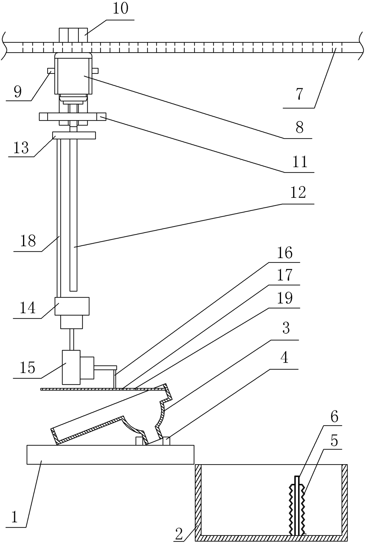
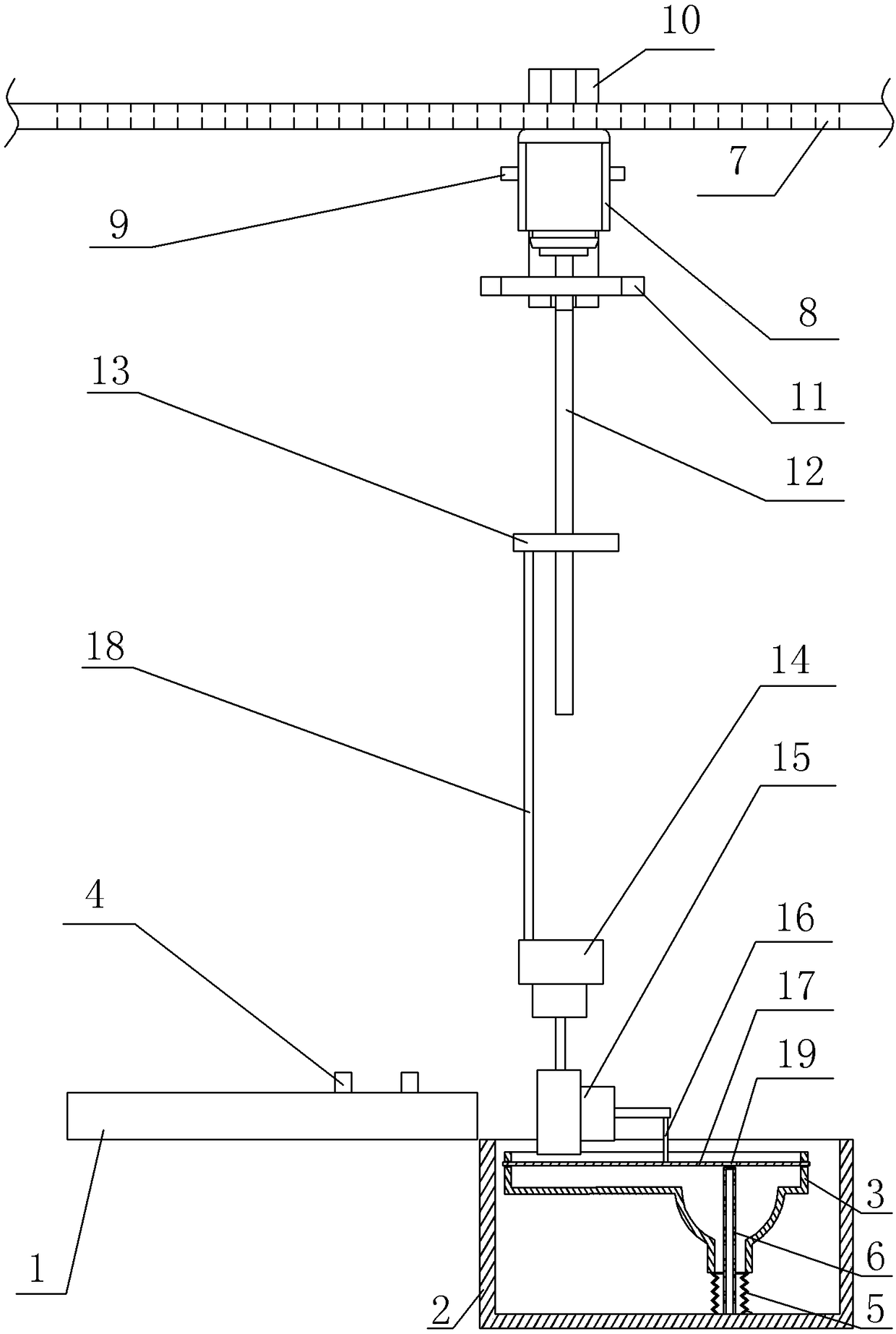
[0019] The reference signs in the drawings of the specification include: conveyor belt 1, glaze dip tank 2, squatting pan 3, blocking block 4, corrugated pipe 5, glaze spray pipe 6, rack 7, servo motor 8, support plate 9, gear rod 10. Incomplete gear 11, screw rod 12, nut seat 13, lifting cylinder 14, push-pull cylinder 15, connecting rod 16, blocking rod 17, lifting rod 18, and through hole 19.

[0020] The glazing process for sanitary ware includes the following steps:

[0021] Step 1: Prepare a figure 1 , 2 The sanitary ware glazing equipment shown includes a conveyor belt 1, a glaze dip tank 2, a transfer mechanism and a lifting mechanism. The conveyor belt 1 is arranged on the frame and can convey the squatting pan 3 from back to front. The conveyor belt 1 is fixed with a block 4 capable of positioning the squatting pan 3.

[0022] The glaze dip tank 2 is located on the right side of the c...


PUM


Abstract

The invention relates to the field of production of sanitary appliances and in particular relates to a glazing technology for the sanitary appliances. The glazing technology comprises the following steps: step 1: preparing sanitary appliance glazing equipment comprising a conveyor belt, a glaze immersing tank, a transferring mechanism and a lifting mechanism, wherein a glaze spraying mechanism isarranged in the glaze immersing tank; step 2: placing a squatting pan on the conveyor belt; when conveying the squatting pan to the lifting mechanism, driving the squatting pan to move upward throughthe lifting mechanism; step 3: driving the squatting pan to move in the direction toward the glaze immersing tank through the transferring mechanism; step 4: when moving the squatting pan to the upperside of the glaze spraying mechanism, driving the squatting pan to move downward through the transferring mechanism; step 5: when the glaze spraying mechanism is in contact with the squatting pan, spraying glaze to an inner side of the squatting pan by the glaze spraying mechanism; meanwhile, glazing an outer side of the squatting pan in a process of downward moving the squatting pan in the glazeimmersing tank. By adopting the glazing technology provided by the invention, the glazing speed and quality can be both considered; meanwhile, a water inlet of the squatting pan also can be preventedfrom being blocked and a glaze layer is prevented from being damaged.

Description

Technical field [0001] The invention relates to the field of ceramic sanitary ware production, in particular to a glazing process for sanitary ware. Background technique [0002] At present, most manufacturers of daily-use ceramics use manual methods for glazing. For example, during the glazing process of squatting pans, workers immerse the body of the squatting pan in the glaze, and take it out after staying for a period of time. The glaze remains. The surface of the squatting pan body. Compared with spray glazing, this glazing method has higher processing efficiency, but the glazing is not delicate, especially for the glazing of the inner wall of the squatting pan, the fineness of the inner wall directly determines the quality of the product But at the same time, for the outer wall of the squatting pan, the glaze fineness is not as high as that of the inner wall of the squatting pan. [0003] While immersing the body of the squatting pan into the glaze for glazing, since the wa...

Claims


Application Information

Patent Timeline
Patent Type & Authority Applications(China)
IPC IPC(8): C04B41/86
CPCC04B41/5022C04B41/86C04B41/4543C04B41/4539
Inventor 唐其云罗永德李林
Owner CHONGQING CONCAST SANITARY WARE
Learn More