Omnidirectional-radiation broadband circular polarization antenna

A circularly polarized antenna and omnidirectional antenna technology, which is applied to antennas, electrical components, etc., can solve the problems of inability to realize broadband circularly polarized electromagnetic waves, limited bandwidth, and weak mechanical structure, and achieves high gain, high frequency bandwidth, The effect of low circular polarization axis ratio

Inactive Publication Date: 2018-09-14
UNIV OF ELECTRONICS SCI & TECH OF CHINA
View PDF4 Cites 6 Cited by
  • Summary
  • Abstract
  • Description
  • Claims
  • Application Information

AI Technical Summary

Problems solved by technology

[0003] The invention patent with application number 2011204915073 "An Omnidirectional Circularly Polarized Antenna" discloses an omnidirectional circularly polarized antenna formed by a dish cone antenna and a circularly polarized cover. The dish cone antenna generates vertically polarized electromagnetic waves. Then use the circular polarization cover to reverse the polarization to obtain circularly polarized electromagnetic waves; however, there is only one layer of rectangular polarization strips surrounding the antenna in this antenna, and the bandwidth is limited, which cannot meet the requirements of broadband circularly polarized electromagnetic waves, and the mechanical weak structure

Method used


Image

  • Omnidirectional-radiation broadband circular polarization antenna
  • Omnidirectional-radiation broadband circular polarization antenna
  • Omnidirectional-radiation broadband circular polarization antenna

Examples


Embodiment

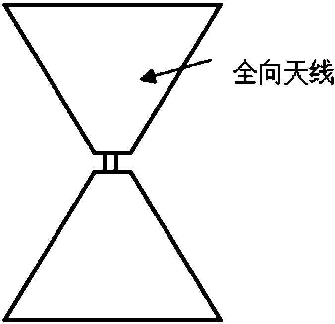
[0035] A broadband circularly polarized antenna with omnidirectional radiation, such as figure 1 As shown, it includes two parts: a biconical antenna that generates linearly polarized electromagnetic waves and a hollow cylindrical circular polarizer located outside the biconical antenna;

[0036] like figure 2 Shown is a cross-sectional view of a biconical antenna; the biconical antenna is 25.5 mm high and 34 mm in diameter at the top of the cone, and is used to generate linearly polarized electromagnetic waves that radiate omnidirectionally at 8-18 GHz.

[0037] like image 3 As shown, the hollow cylindrical circular polarizer includes 4 layers of coaxial meander-type metal polarization grids, wherein each layer of meander-type metal polarization grids is printed on the side of the hollow dielectric cylinder with a plurality of identical Composed of broken-line grids, each broken-line grid is composed of broken-line grid units ( Figure 8 ) is periodically repeated to ob...


PUM


Abstract

The invention discloses an omnidirectional-radiation broadband circular polarization antenna, which belongs to the technical field of wireless communication equipment. The circular polarization antenna comprises an omnidirectional antenna and a hollow cylindrical circular polarizer located outside the omnidirectional antenna, wherein the axes of the omnidirectional antenna and the hollow cylindrical circular polarizer are coincident and the distance is 0.2 lambda0 to 0.4 lambda0; the hollow cylindrical circular polarizer comprises n layers of coaxial broken line-type metal polarization gratings, each broken line-type metal polarization grating layer is formed by parallelly-arranged broken line gratings covering the side surface of a hollow dielectric cylinder, broken line grating units arerepeated periodically to form each broken line grating, the line width of the broken line grating unit is 4*10<-3> lambda0 to 0.03 lambda0, the height is 0.1 lambda0 to 0.3 lambda0, the width of a U-type part is 0.025 lambda0 to 0.1 lambda0, the gap between adjacent broken line gratings is 0.1 lambda0 to 0.5 lambda0, and the included angle between the axis of the broken line grating unit and theaxis of the hollow cylindrical circular polarizer is 45 DEG. According to the broadband circular polarization antenna provided in the invention, an antenna radiating circular polarization electromagnetic waves can be obtained in a polarization torsion mode, and the antenna is good in omnidirectional performance, low in a circular polarization axial ratio, wide in frequency band and high in gains.

Description

technical field [0001] The invention belongs to the technical field of wireless communication equipment, and in particular relates to a broadband circularly polarized antenna with omnidirectional radiation. Background technique [0002] As a device for transmitting and receiving electromagnetic waves, the performance of the antenna will directly affect the efficiency of the communication system. With the rapid development of wireless communication technology for information exchange, the antenna must have certain anti-interference ability. Because the antenna itself has polarization characteristics, it is very important to select an appropriate antenna polarization mode in terms of interference signal suppression and transmission signal reception. That is to say, on the one hand, the antenna needs to work in a certain frequency band and achieve a certain gain, and on the other hand, it must have the ability to control the beam direction and polarization. Purely linearly po...

Claims


Application Information

Patent Timeline
Patent Type & Authority Applications(China)
IPC IPC(8): H01Q15/24
CPCH01Q15/244
Inventor 黄麒力宗显政文成纲聂在平
Owner UNIV OF ELECTRONICS SCI & TECH OF CHINA
Why Eureka
Try Eureka