Omnidirectional radiation oscillator array antenna for coupling feed

A technology of coupling feeding and omnidirectional radiation, applied in the directions of antenna, antenna array, radiating element structure, etc., can solve the problems of poor omnidirectional working frequency band, narrow omnidirectional antenna bandwidth and large size, etc., and achieve good omnidirectionality , the feeding form is compact and the size is small

Active Publication Date: 2012-10-31
HARBIN INST OF TECH
View PDF2 Cites 3 Cited by
  • Summary
  • Abstract
  • Description
  • Claims
  • Application Information

AI Technical Summary

Problems solved by technology

[0004] The purpose of the present invention is to solve the problems of the existing omnidirectional antenna with narrow bandwidth, low gain, poor omnidirectionality and large size in the working frequency band, and further provide a coupling-feed omnidirectional radiating oscillator array antenna

Method used


Image

  • Omnidirectional radiation oscillator array antenna for coupling feed
  • Omnidirectional radiation oscillator array antenna for coupling feed
  • Omnidirectional radiation oscillator array antenna for coupling feed

Examples


specific Embodiment approach 1

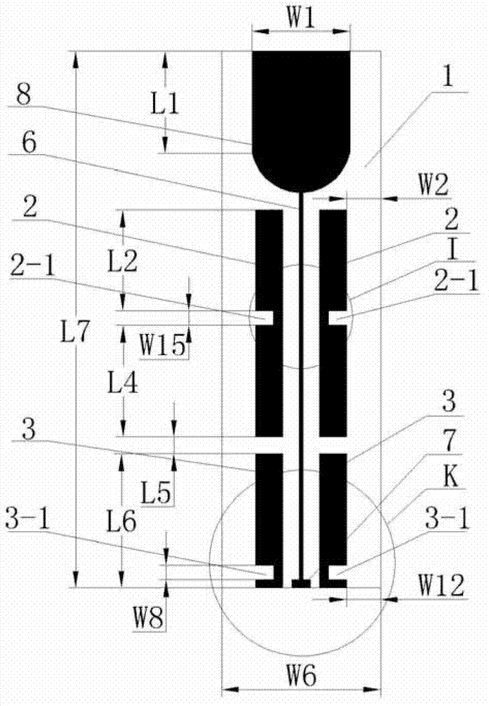
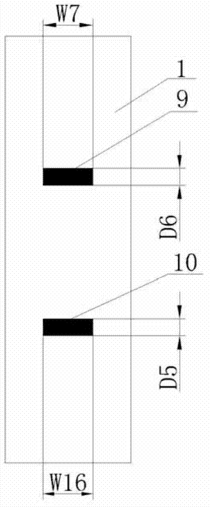
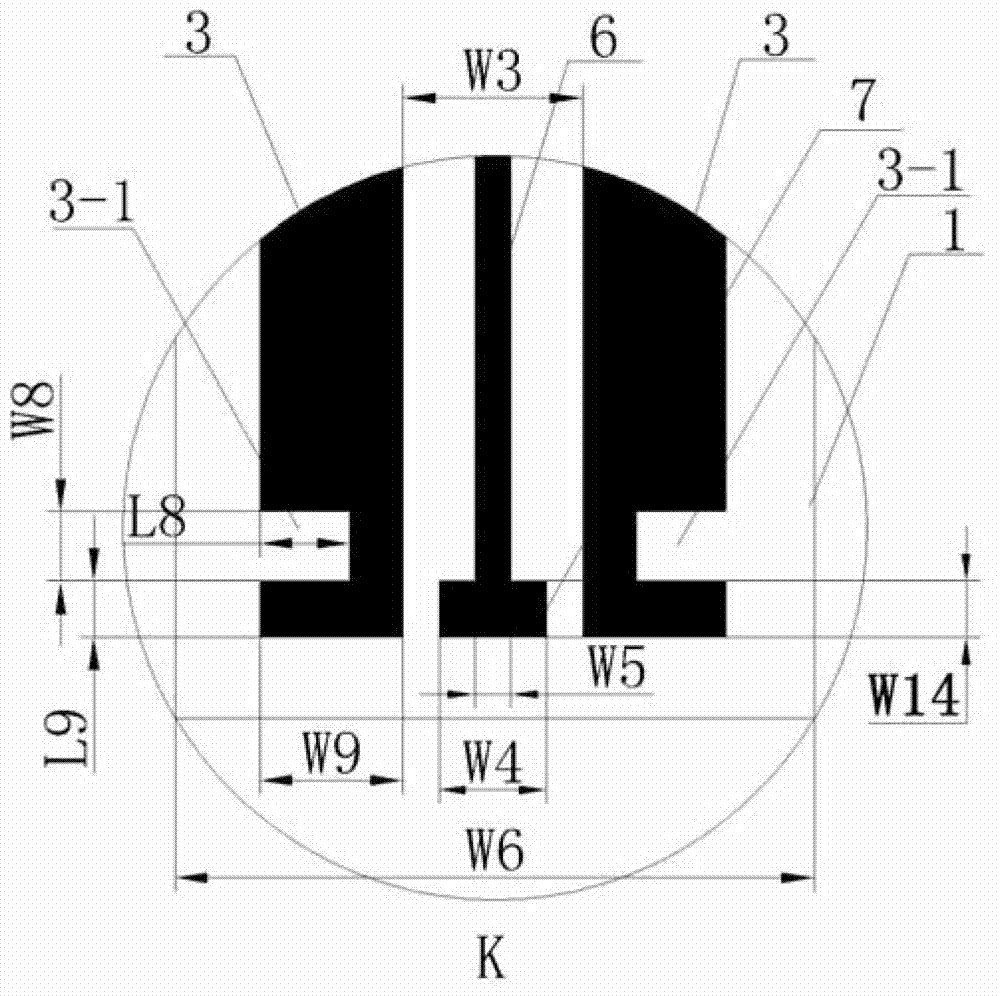
[0008] Specific implementation mode one: combine Figure 1-Figure 6 This embodiment is described. The omnidirectional radiation dipole array antenna for coupling and feeding in this embodiment includes a dielectric plate 1 and a coplanar waveguide central feeder 6. The antenna also includes a feeding port matching stub 7, a radiating terminal load 8 and two A group of oscillators, the front plate of the dielectric board 1 is printed with a coplanar waveguide central feeder 6, a feeding port matching branch 7, a radial terminal load 8 and two groups of oscillators, and the lower end of the coplanar waveguide central feeder 6 matches the feeding port The branches 7 are connected, and the upper end of the coplanar waveguide central feeder 6 is connected to the radial terminal load 8. Each set of vibrators includes the first vibrator 2 and the second vibrator 3. Both the first vibrator 2 and the second vibrator 3 are rectangular. Two sets of vibrators It is arranged symmetrically ...

specific Embodiment approach 2

[0010] Specific implementation mode two: combination figure 1 To describe this embodiment, the dielectric board 1 in this embodiment is an epoxy glass cloth laminated board with a thickness of 1.4 mm to 1.6 mm and a relative dielectric constant of 4.4. In this way, the epoxy glass cloth laminated board of this embodiment is made of FR-4 grade material, which has good electrical performance stability under high humidity, and meets the design requirements and actual needs. Others are the same as in the first embodiment.

specific Embodiment approach 3

[0011] Specific implementation mode three: combination figure 1 To illustrate this embodiment, the radial terminal load 8 described in this embodiment is a combined shape, the combined shape is composed of a rectangle and a semicircle, the short side of the rectangle is in the same plane as the diameter of the semicircle, and the short side of the rectangle is in the same plane as the diameter of the semicircle. Semicircles are equal in diameter. In such a configuration, the combined radiating terminal load plays a role that ordinary loads do not have, that is, radiates electromagnetic waves, thereby further improving the gain of the antenna of the present invention. Meet the design requirements and actual needs. Others are the same as in the first or second embodiment.


PUM


Abstract

An omnidirectional radiation oscillator array antenna for coupling feed relates to a printing antenna and resolves the problem that the existing omnidirectional antenna is narrow in bandwidth, low in gain, poor in omnidirectional performance in working band and larger in size. The antenna comprises a media plate and a coplanar waveguide center feeder. The antenna further comprises a feed port matching branch knot, radiation type terminal load and two groups of oscillators. The coplanar waveguide center feeder, the feed port matching branch knot, the radiation type terminal load and the two groups of oscillators are printed on the front plate face of the media plate, the lower end of the coplanar waveguide center feeder is connected with the feed port matching branch knot, and the upper end of the coplanar waveguide center feeder is connected with the radiation type terminal load. Each group of vibrators comprise a first vibrator and a second vibrator which are rectangular, the two groups of vibrators are symmetrically arranged along the coplanar waveguide center feeder, and a first horizontal feeder and a second horizontal feeder are printed on the back plate face of the media plate. The antenna is used for the technical field of radio engineering.

Description

technical field [0001] The invention relates to a printed antenna, in particular to an omnidirectional radiation printed antenna, which belongs to the field of radio technology. Background technique [0002] The printed antenna is an antenna made with modern printed circuit board technology. The omnidirectional antenna is an antenna that has basically no difference in radiation in the horizontal plane and has directional radiation in the vertical plane, that is, on the horizontal pattern It is manifested as 360° uniform radiation, which is commonly referred to as non-directional. Since the development of omnidirectional antennas, various forms have been produced in structure, such as monopole, dipole, biconical, helical antenna, etc., and the realization methods mainly include parallel feed and series feed. It is widely used in some special communication systems such as point-to-multipoint base station-to-terminal communication and satellite communication system. [0003] ...

Claims


Application Information

Patent Timeline
Patent Type & Authority Applications(China)
IPC IPC(8): H01Q1/38H01Q13/00H01Q21/00
Inventor 林澍刘曦马欣茹田雨荆丽雯陆加王立娜王力卓
Owner HARBIN INST OF TECH
Why Eureka
Try Eureka