A sling for hoisting an adjustable transmission shaft

A transmission shaft and hoisting technology, applied in the field of spreaders, can solve problems such as affecting the production process, falling off and loss of the transmission shaft, etc., and achieve the effects of adjustable space size, stable hoisting, and strong gripping force.

Inactive Publication Date: 2019-05-21
HENAN XINZHOU TRANSMISSION MACHINERY CO LTD
View PDF7 Cites 0 Cited by
  • Summary
  • Abstract
  • Description
  • Claims
  • Application Information

AI Technical Summary

Problems solved by technology

[0002] In the detection or assembly process of the transmission shaft, some heavy transmission shafts need to be hoisted for corresponding detection or assembly. In the production workshop, a cantilever crane is usually used for hoisting. The traditional hoisting method mainly uses wire ropes to lift the transmission shaft. Lifting after fixing, because the transmission shaft is heavier and smoother, so the transmission shaft is easier to fall off, causing unnecessary losses, so special slings are needed. The existing transmission shaft slings mainly have the following problems: first , the spreader is not adjustable and cannot adapt to transmission shafts of different thicknesses, and the adaptability is not strong; secondly, the spreader has insufficient grip and balance, which may easily cause the transmission shaft to fall off, causing unnecessary losses and affecting the production process; therefore, in order to solve Above-mentioned problem, it is very necessary to develop a kind of adjustable transmission shaft hoisting sling

Method used


Image

  • A sling for hoisting an adjustable transmission shaft
  • A sling for hoisting an adjustable transmission shaft
  • A sling for hoisting an adjustable transmission shaft

Examples


Embodiment Construction

[0015] The technical solution of the present invention will be further specifically described below in conjunction with the accompanying drawings.

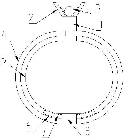
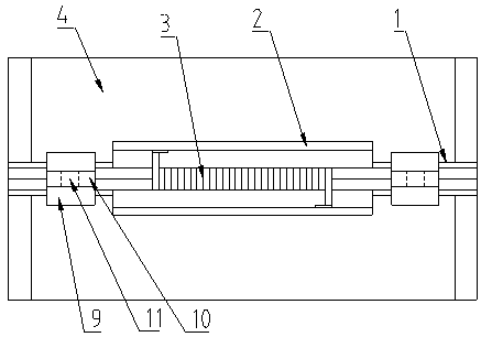
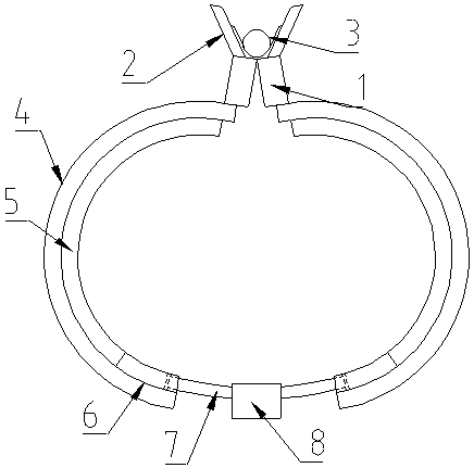
[0016] Such as figure 1 , figure 2 , image 3 As shown, a hoisting tool for adjustable transmission shaft, including movable plate 1, splint 2, torsion spring 3, connecting hoop 4, buffer layer 5, cavity 6, guide rod 7, connecting block 8, hanging base 9 , hanging plate 10 and hanging through hole 11.

[0017] Wherein, the movable board 1 is two vertical boards parallel to each other. Preferably, the tops of the two movable boards 1 are connected together by a hinge, which is convenient to use. The movable board 1 is provided with a V-shaped splint 2, preferably , the movable plate 1 and the splint 2 are set in an integrated structure, which makes the whole device more durable, a torsion spring 3 is arranged between the splints 2, and a semicircular connecting hoop 4 is fixedly connected to the bottom of the movable plate 1, a...


PUM


Abstract

The invention discloses a lifting tool for lifting with an adjustable transmission shaft. The tool comprises movable plates, clamping plates, a torsion spring, a connecting hoop, a buffer layer, a cavity, a guide rod, a connecting block, hanging bases, hanging plates and hanging through holes, wherein the movable plate is two vertical plates which are parallel to each other, the V-shaped clampingplates are arranged on the movable plate, the torsion spring is arranged between the clamping plates, and the semicircular connecting hoop is fixedly connected below the movable plate; the buffer layer is arranged on the inner layer of the connecting hoop, the cavity is formed in the tail end of the buffer layer and located on the connecting hoop, and the arc-shaped guide rod is slidably connectedin the cavity; the outer end of the guide rod is fixedly connected with the connecting block, and the hanging bases are further arranged on the two sides of the top end of the movable plate; and thevertical hanging plates are fixedly arranged on the hanging bases, the hanging through holes are formed in the hanging plates. In general, the lifting tool for lifting with the adjustable transmissionshaft has the advantages of being adjustable, high in adaptability, high in grasping force, good in balance performance and stable in hoisting.

Description

technical field [0001] The invention relates to a sling, in particular to a sling for hoisting an adjustable transmission shaft. Background technique [0002] In the detection or assembly process of the transmission shaft, some heavy transmission shafts need to be hoisted for corresponding detection or assembly. In the production workshop, a cantilever crane is usually used for hoisting. The traditional hoisting method mainly uses wire ropes to lift the transmission shaft. Lifting after fixing, because the transmission shaft is heavier and smoother, so the transmission shaft is easier to fall off, causing unnecessary losses, so special slings are needed. The existing transmission shaft slings mainly have the following problems: first , the spreader is not adjustable and cannot adapt to transmission shafts of different thicknesses, and the adaptability is not strong; secondly, the spreader has insufficient grip and balance, which may easily cause the transmission shaft to fal...

Claims


Application Information

Patent Timeline
Patent Type & Authority Patents(China)
IPC IPC(8): B66C1/30B66C1/44
CPCB66C1/30B66C1/44
Inventor 尚梦鸽尚亚民
Owner HENAN XINZHOU TRANSMISSION MACHINERY CO LTD
Why Eureka
Try Eureka