Radial shearing limit experiment device for axis parts

A technology of shaft parts and experimental devices, applied in measuring devices, using stable shear force to test material strength, instruments, etc., can solve the problems of difficulty in operation, insufficient shear strength, high cost, and ensure the accuracy of sliding fit. Effect

Active Publication Date: 2018-09-18
ANYANG INST OF TECH
View PDF7 Cites 3 Cited by
  • Summary
  • Abstract
  • Description
  • Claims
  • Application Information

AI Technical Summary

Problems solved by technology

[0002] Safety production is the top priority of production enterprises, and some equipment has safety accidents and even casualties due to insufficient shear strength during design. Therefore, the strength of parts requires not only theoretical calculations, but also strength experiments. The current shear The experimental device for shear strength is complex in structure, difficult to operate, and high in cost

Method used


Image

  • Radial shearing limit experiment device for axis parts
  • Radial shearing limit experiment device for axis parts
  • Radial shearing limit experiment device for axis parts

Examples


Embodiment Construction

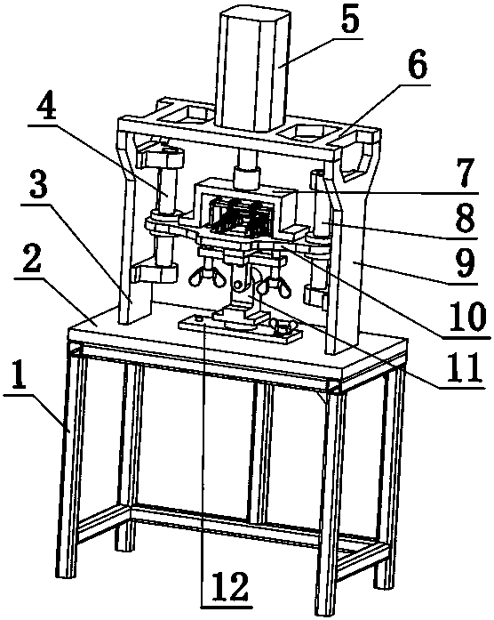
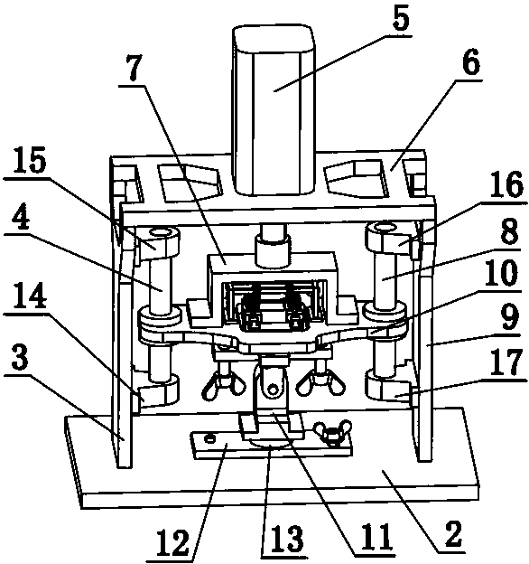
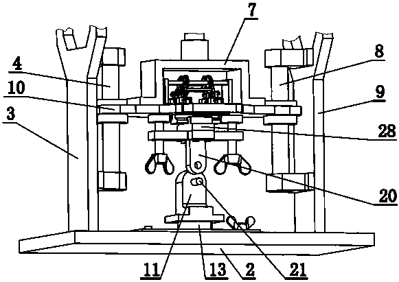
[0034] combine Figure 1-10, a radial shear limit test device for shaft parts of the present invention, comprising a lower support frame 1, a lower fixed plate 2, a left vertical plate 3, a left guide post 4, a hydraulic cylinder 5, an upper fixed plate 6, and a connecting frame 7. Right guide column 8, right vertical plate 9, lifting plate 10, lower shear seat 11, swing plate 12, pressure sensor 13, left lower seat 14, left upper seat 15, right upper seat 16, right lower seat 17, upper shear Cutting seat 20, column pin 22, dish nut 23, stud 24, dish bolt 25, compression shoe 26, loading guide rail 27, loading slider 28, left support seat 29, left guide rail flexible support device 30 , rear support bar 31, front support bar 32, right side guide rail flexible support device 33, rear synchronous bar 34, front synchronous bar 35, right support seat 36, control system, described right side guide rail flexible support device 33 comprises right front gear 3301, right rear gear 330...


PUM


Abstract

The invention discloses a radial shearing limit experiment device for axis parts. The radial shearing limit experiment device comprises a hydraulic cylinder, an upper fixed plate (6), a lifting plateand a control system, wherein a left right vertical plate and a right side vertical plate are respectively fixed on the left and right sides of a lower fixed plate, guiding mechanisms which are provided with lifting plates and move along the up-down direction are arranged on the left right vertical plate and the right side vertical plate, the upper fixed plate is fixed at the upper ends of the left right vertical plate and the right side vertical plate, and the hydraulic cylinder is fixed on the upper fixed plate; a connecting frame is fixed by a piston rod of the hydraulic cylinder, the lifting plate is fixed by the connecting frame, a left side guide rail flexible supporting device and a right side guide rail flexible supporting device are arranged on the lifting plate, a loading guide rail is fixed by the left side guide rail flexible supporting device and a right side guide rail flexible supporting device, a loading sliding block is mounted on the loading guide rail, an upper shearing seat is fixed on the loading sliding block, a butterfly bolt is screwed to the upper shearing seat, and an upper pin hole is formed in the upper shearing seat; and a lower pin hole is formed in alower shearing seat, the lower shearing seat is fixed on a swing plate through a pressure sensor, and the fixed position of the swing plate on the lower fixed plate can be adjusted. By utilizing the left side guide rail flexible supporting device and the right side guide rail flexible supporting device, the load can be completely borne by the butterfly bolt.

Description

technical field [0001] The invention relates to a shear limit test device, in particular to a radial shear limit test device for shaft parts. Background technique [0002] Safety production is the top priority of production enterprises, and some equipment has safety accidents and even casualties due to insufficient shear strength during design. Therefore, the strength of parts requires not only theoretical calculations, but also strength experiments. The current shear The experimental device for shear strength is complex in structure, difficult to operate, and high in cost. [0003] This application adopts automatic control, collects the data of pressure sensor in real time, and accurately measures the radial shear strength of shaft parts; The synchronous rod realizes the horizontal lifting of the loading guide rail connected by the double flexible device; the position of the upper shearing seat and the lower shearing seat can be adjusted to realize the coaxiality of the up...

Claims


Application Information

Patent Timeline
Patent Type & Authority Applications(China)
IPC IPC(8): G01N3/24G01N3/02
CPCG01N3/02G01N3/24G01N2203/0025G01N2203/0048
Inventor 马洪儒吴贵军国秀丽张文帆
Owner ANYANG INST OF TECH
Why Eureka
Try Eureka