Sewage disinfection device for sewage sterilization

A technology of sterilization treatment and disinfection device, which is applied in the direction of light water/sewage treatment, water/sludge/sewage treatment, magnetic field/electric field water/sewage treatment, etc. It can solve the problems of low catalyst utilization, blocking ultraviolet radiation, and affecting disinfection Effect and other issues, to achieve the effect of good practicability, increased mixing degree, and degradation of organic pollutants

Inactive Publication Date: 2018-09-28
UNIV OF SHANGHAI FOR SCI & TECH
View PDF6 Cites 0 Cited by
  • Summary
  • Abstract
  • Description
  • Claims
  • Application Information

AI Technical Summary

Problems solved by technology

However, there are still some problems in the actual use of the traditional sewage disinfection device using ultraviolet rays and the traditional photocatalytic sewage disinfection device using photocatalytic reaction for disinfection.
For example, the ultraviolet lamp of the traditional ultraviolet disinfection device is placed in the water body, and a large amount of impurities contained in the sewage will adhere to the wall of the ultraviolet lamp tube, which will block the emission of ultraviolet rays, thus affecting the disinfection effect
However, the traditional photocatalytic reactor is affected by many factors such as light source and catalyst, which can easily lead to insufficient reaction and low utilization rate of catalyst, which will affect the disinfection effect.

Method used


Image

  • Sewage disinfection device for sewage sterilization
  • Sewage disinfection device for sewage sterilization
  • Sewage disinfection device for sewage sterilization

Examples


Embodiment Construction

[0012] The present invention will be further described below in conjunction with the accompanying drawings.

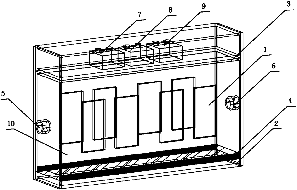
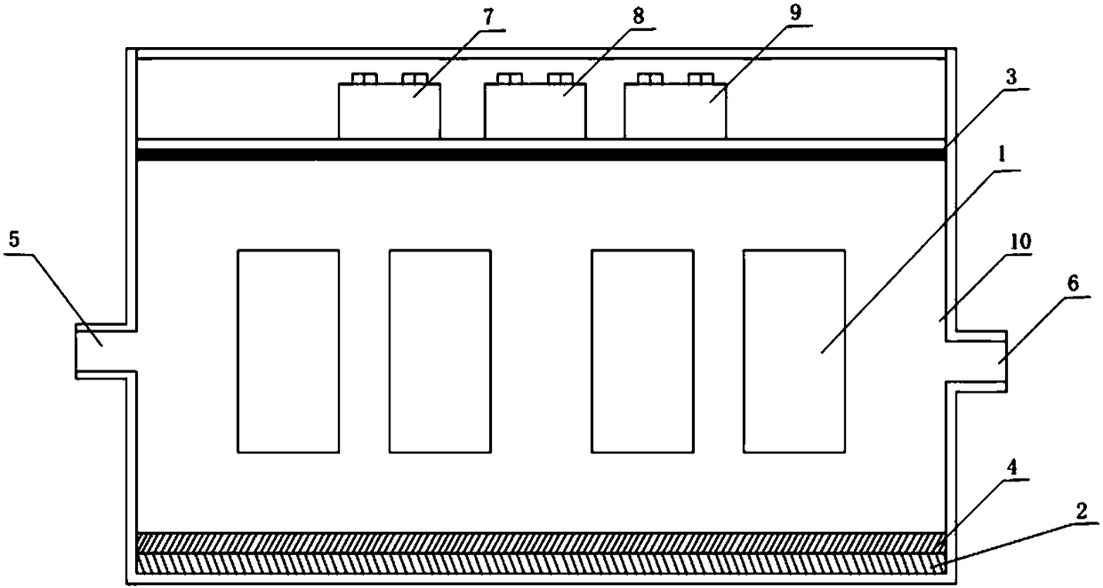
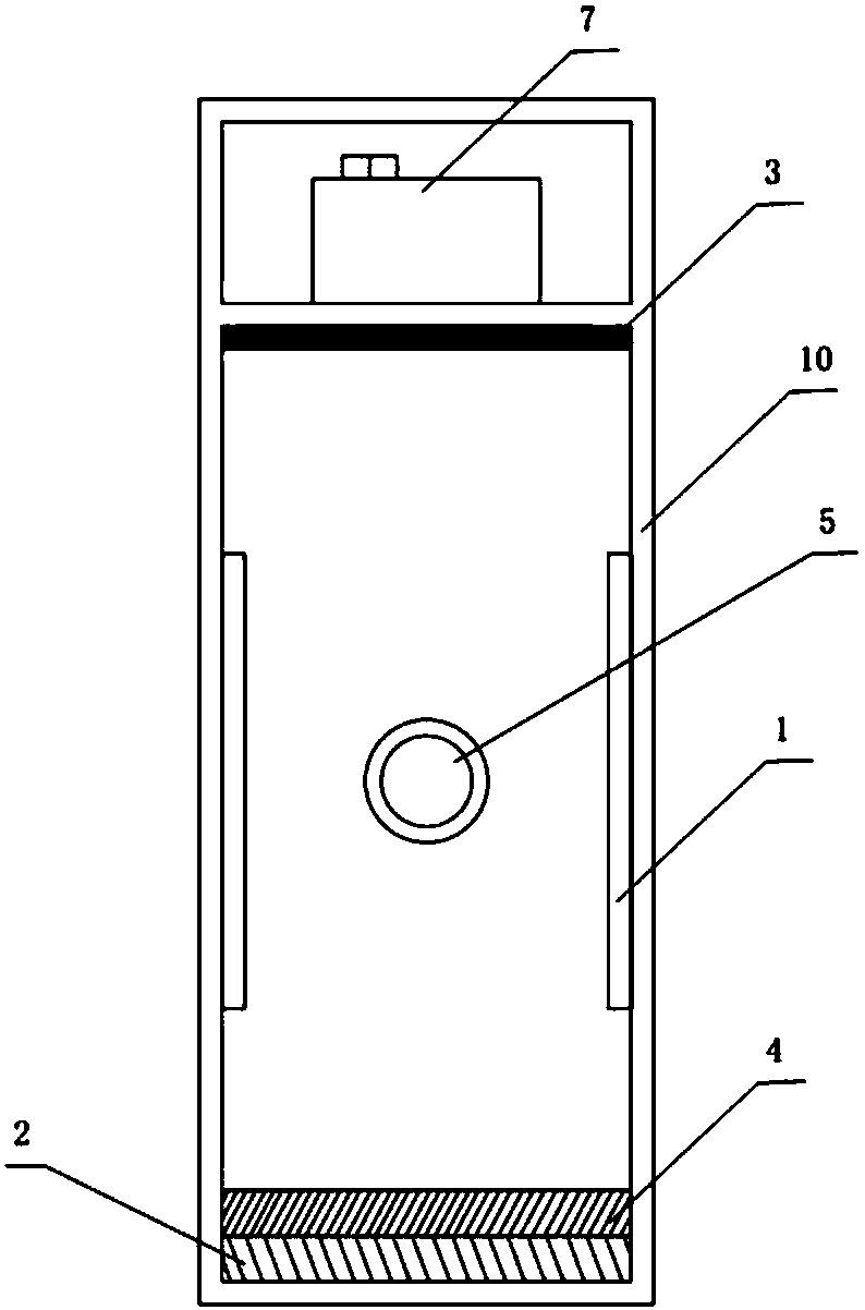
[0013] Such as Figure 1 to Figure 3 As shown, a sewage disinfection device for sewage sterilization treatment, including energized electrode 1, magnetic field generating device 2, photocatalytic light source 3, photocatalyst layer 4, water inlet pipe 5, water outlet pipe 6, voltage controller 7, A magnetic field intensity controller 8, a light source intensity regulator 9, and a pool body 10.

[0014] The two ends of the pool body 10 are respectively provided with a water inlet pipe 5 and a water outlet pipe 6, the inner wall of the pool body 10 is provided with a energized electrode 1, the upper end of the pool body 10 is provided with a photocatalytic light source 3, and the upper end of the photocatalytic light source 3 is provided with a voltage controller 7 , a magnetic field intensity controller 8, a light source intensity regulator 9, a photocatalyst layer 4 i...


PUM


Abstract

The invention relates to a sewage disinfection device for sewage sterilization. The sewage disinfection device is characterized in that a water intake pipe and a water drain pipe are arranged at bothends of a tank body; an energizing electrode is arranged at the inner wall of the tank body; a photocatalysis light source is arranged at the upper part of the tank body; a voltage controller, a magnetic field intensity controller and a light source intensity adjuster are arranged at the upper surface of the photocatalysis light source; a photocatalyst layer is arranged at the lower part of the tank body, a magnetic field generator is arranged at the lower surface of the photocatalyst layer, and the voltage controller is electrically connected with the energizing electrode; the light source intensity adjuster is electrically connected with the photocatalysis light source. The sewage disinfection device has the advantages that sewage is radiated by light and is in contact with the photocatalyst layer to be subjected to the photocatalysis reaction, and microorganisms in the water can be inhibited and killed by a magnetic field; after the electrode is energized, the sewage is subjected tothe mixing and reverse pumping action forces under the functions of the electrode and the magnetic field, so that the problem of incomplete reaction of the sewage in the tank body is effectively solved, the mixing degree of the sewage in the device is increased, and the hydraulic retention time is long; the microorganisms in the sewage can be effectively inhibited and killed, the organic pollutants can be degraded, and the practicality is good.

Description

technical field [0001] The invention relates to a sewage disinfection device, in particular to a sewage disinfection device for sewage sterilization treatment. Background technique [0002] At present, in the process of sewage treatment, the disinfection of sewage generally adopts ultraviolet light for sterilization and photocatalytic disinfection. Ultraviolet disinfection is to place the ultraviolet lamp tube in the sewage, emit ultraviolet rays into the sewage through the ultraviolet lamp tube, and use ultraviolet rays to sterilize the sewage. Because ultraviolet disinfection has a broad spectrum, it can kill most of the bacteria and viruses in the sewage. The efficiency of sterilization and disinfection is high, so it is often used as the preferred disinfection method in the process of sewage disinfection. Photocatalytic disinfection, that is, the use of light and the reaction of sewage and catalysts to treat sewage for disinfection, is a sewage treatment method that app...

Claims


Application Information

Patent Timeline
Patent Type & Authority Applications(China)
IPC IPC(8): C02F1/30C02F1/48C02F101/30
CPCC02F1/30C02F1/48C02F2101/30C02F2303/04C02F2305/10
Inventor 邓保庆徐钰颖汤家玮高晶李晓王佳徐良田龙飞沐贤维
Owner UNIV OF SHANGHAI FOR SCI & TECH
Why Eureka
Try Eureka