AI technical title is built by Patsnap AI team. It summarizes the technical point description of the patent document.
An assembly method and clamp technology, applied in the direction of sleeve/socket connection, pipe/pipe joint/pipe fitting, passing element, etc., can solve the problem that bolts affect assembly efficiency and safety.
Pending Publication Date: 2018-10-12
QINZHOU UNIV
View PDF8 Cites 1 Cited by
Summary
Abstract
Description
Claims
Application Information
AI Technical Summary
This helps you quickly interpret patents by identifying the three key elements:
Problems solved by technology
Method used
Benefits of technology
Problems solved by technology
[0003] The invention proposes a new clamp and its assembly method, which solves the problem in the prior art that when the clamp is used, the bolt slips from the U-shaped clamp groove and affects the assembly efficiency and safety.
Method used
Image
Click on the blue label to locate the original text in one second.
Reading with bidirectional positioning of images and text.
Examples
Embodiment 1
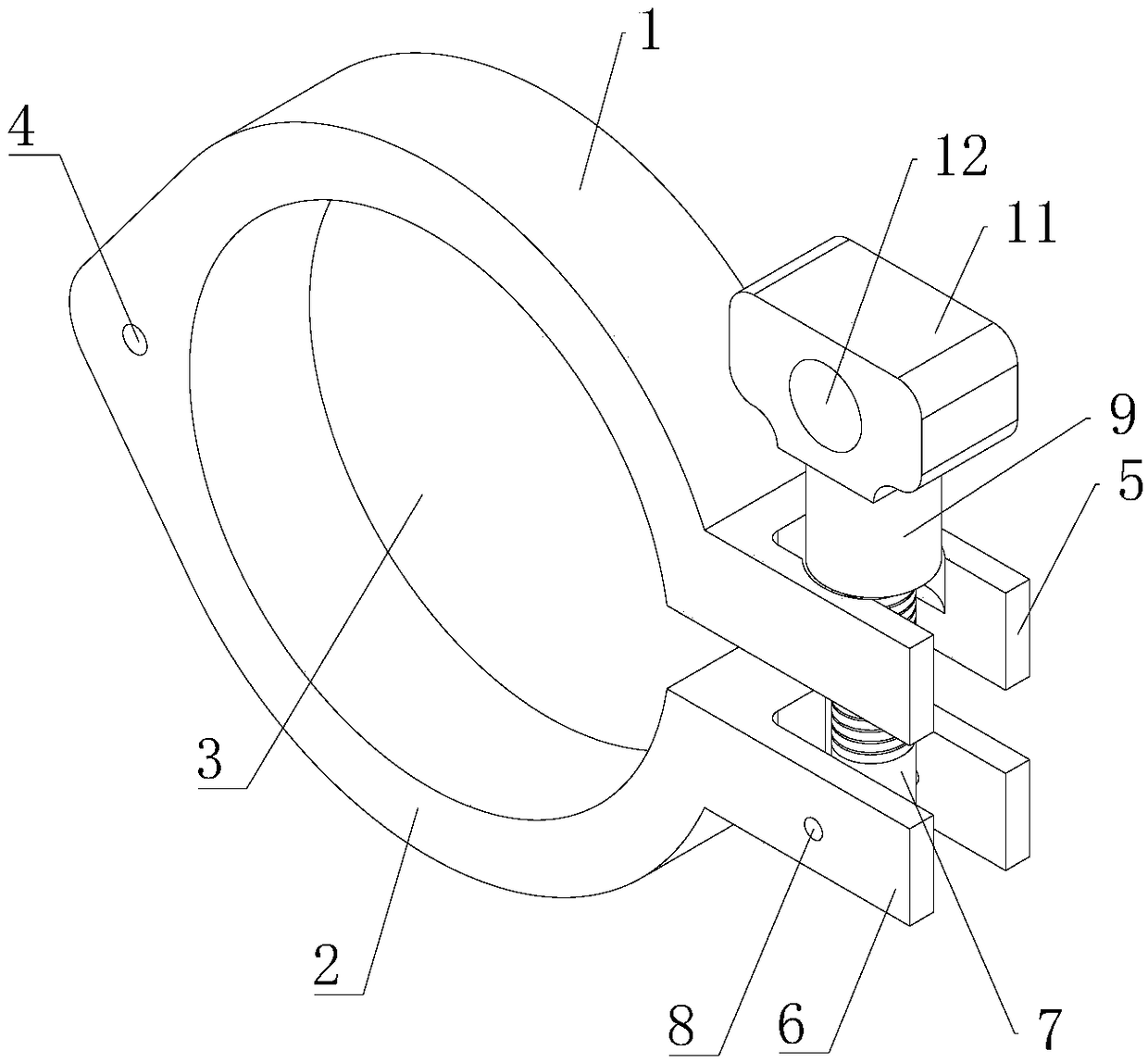
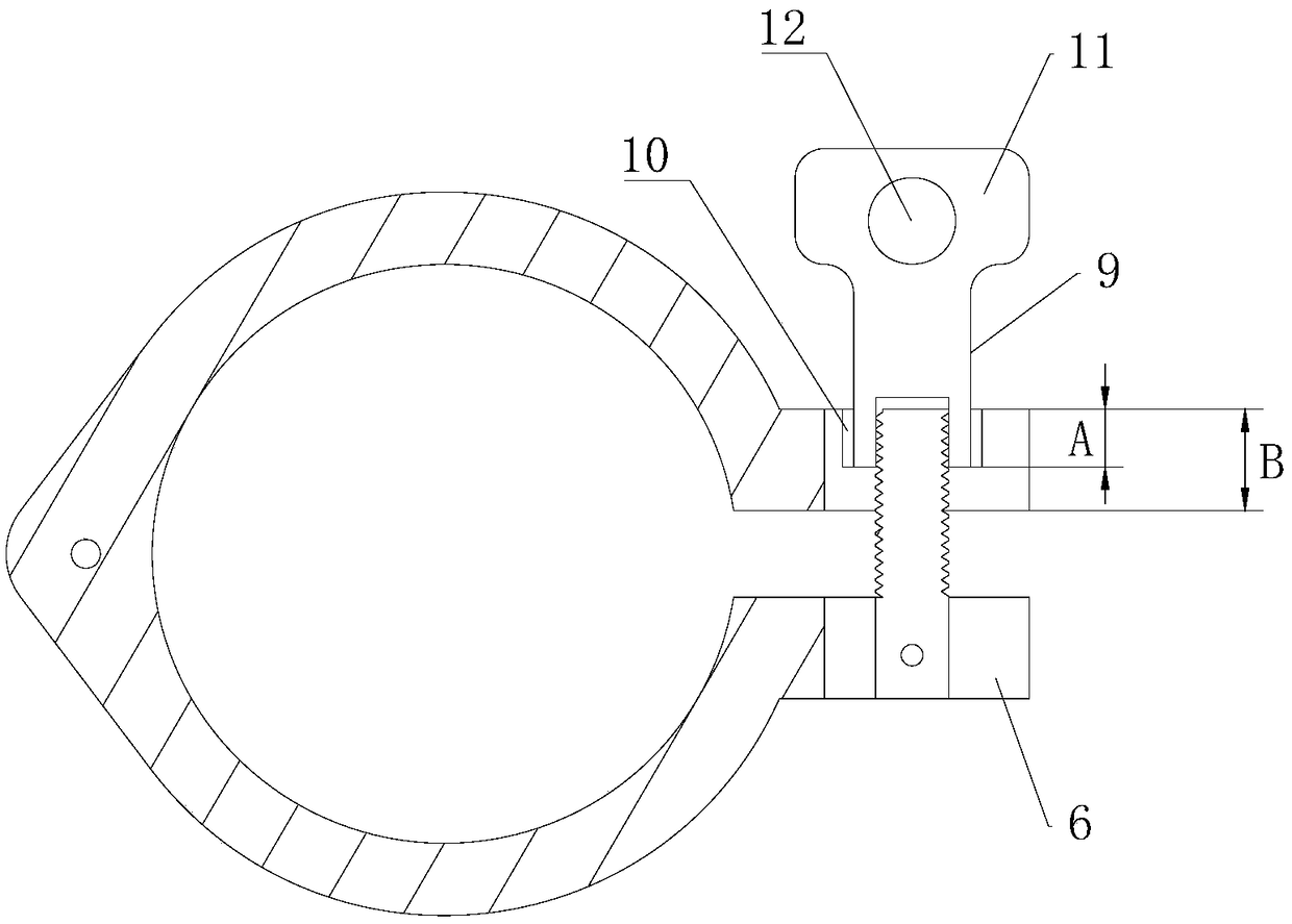
[0029] like Figure 1 to Figure 4 As shown, it is an embodiment of the novel clamp of the present invention, which has an upper clamp 1, a lower clamp 2, and a first hinge shaft 4 with the same structure as the common clamp, and the upper clamp 1 and the lower clamp 2 are both It is semicircular, and the two are oppositely arranged, and one end is connected with the first hinge shaft 4, so that the upper clamp 1 and the lower clamp 2 form a circular channel 3, and the two can use the first hinge shaft 4 as the rotation axis Realize opening and closing. When in use, pass the pipes to be connected through the circular passage 3, and use the clamping action of the upper clamp 1 and the lower clamp 2 to realize the connection of the pipelines.
[0030] The other ends of the upper clamp 1 and the lower clamp 2 are fixed with U-shaped clamping grooves, that is, the upper U-shaped clamping groove 5 and the lower U-shaped clamping groove 6, and the upper U-shaped clamping groove 5 an...
Embodiment 2
[0035] The present invention also proposes a novel clamp assembly method, which includes the following sequence steps
[0036] S1. Remove the nut from the bolt, the bolt is rotated out of the U-shaped groove of the upper clamp, and the gap between the upper clamp and the lower clamp is opened;
[0037] S2. Sleeve the upper clamp and the lower clamp on the pipeline to be connected, and merge the upper clamp and the lower clamp;
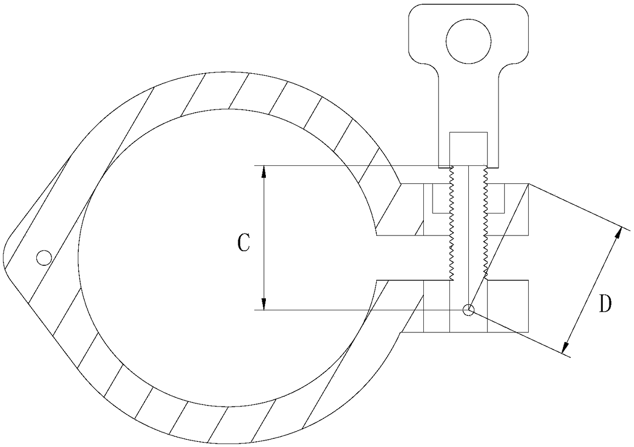
[0038] S3. Rotate the bolt around the second hinge shaft until it is rotated into the U-shaped slot of the upper clamp;
[0039] S4. Screw the nut on the bolt so that the nut is embedded in the groove of the U-shaped groove of the upper clamp;
[0040] S5. Continue to screw the nut until it rests on the bottom surface of the groove.
[0041] In the above step S5, the screwing shaft can be inserted into the screwing hole, and the screwing shaft can be rotated to realize the screwing of the nut.
[0042] The novel clamp and its assembly method of the ...
PUM
Abstract
The invention provides a novel hoop and an assembly method thereof, and solves the problem of influence on the assembly efficiency and safety by slippage of bolts from U-shaped clamping grooves in useof a hoop in the prior art. The hoop comprises a semicircular upper hoop and a semicircular lower hoop; one ends of the upper hoop and the lower hoop are connected through a first hinge shaft; U-shaped clamping grooves are fixed at the other ends of the upper hoop and the lower hoop; and openings of the U-shaped clamping grooves are towards directions far from the upper hoop and the lower hoop. The hoop further comprises bolts inserted in the two U-shaped clamping grooves; a second hinge shaft is arranged on the U-shaped clamping groove of the lower hoop; the extension direction of the secondhinge shaft is perpendicular to the extension directions of the bolts; the second hinge shaft penetrates through one ends of the bolts, and is hinged with the same; the bolts can be rotated in a plane of the lower hoop with the second hinge shaft as a rotating shaft; the other ends of the bolts are in threaded fit with nuts; grooves for accommodating the nuts are formed in the U-shaped clamping grooves of the upper hoop; the radial sizes of the nuts are larger than the openings of the U-shaped clamping grooves; and the nuts butt against the bottom surfaces of the grooves.
Description
technical field [0001] The invention relates to the technical field of clips, in particular to a novel clip with simple structure and convenient use and an assembly method thereof. Background technique [0002] The clamp is a connection device for grooved pipe fittings, valves and pipeline fittings, and is used as a clamp between quick-fit joints. Clamps generally include upper clamps, lower clamps, bolts, nuts and other components. One end of the bolt is fixed on the lower hoop, and a U-shaped slot is set on the upper hoop to allow the bolt to pass through, and the nut is tightened to make the upper and lower hoops gradually move closer together, and the quick-fit joint is tightened. During the actual clamp assembly and disassembly process, especially during the nut tightening and loosening process, the bolts often slip out of the U-shaped groove of the upper clamp, which makes the assembly parts drop and the assembly process is cumbersome, which seriously affects the asse...
Claims
Application Information
Patent Timeline
Application Date:The date an application was filed.
Publication Date:The date a patent or application was officially published.
First Publication Date:The earliest publication date of a patent with the same application number.
Issue Date:Publication date of the patent grant document.
PCT Entry Date:The Entry date of PCT National Phase.
Estimated Expiry Date:The statutory expiry date of a patent right according to the Patent Law, and it is the longest term of protection that the patent right can achieve without the termination of the patent right due to other reasons(Term extension factor has been taken into account ).
Invalid Date:Actual expiry date is based on effective date or publication date of legal transaction data of invalid patent.

