[0021] Hereinafter, the preferred embodiments of the present invention will be described in detail with reference to the accompanying drawings: it should be understood that the preferred embodiments are only for illustrating the present invention, not for limiting the protection scope of the present invention.
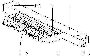
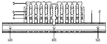
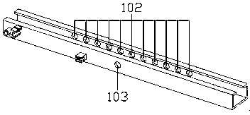
[0022] Such as Figure 1 to 7 As shown, a manually adjustable position memory device in a car seat includes an upper slide rail 1 and a lower rail 2. A position memory device is provided on one side of the upper slide rail 1, and the position memory device is composed of a first The support frame 3, the limit plate 4, and 5-15 memory pins 5 are composed; the first support frame 3 is composed of 4 sides to form a rectangle, and each of the two long sides is provided with 5-15 memory pin sliding holes. 301. The hole distances of the adjacent memory pin sliding holes 301 are the same; the limiting plate 4 is installed on the inner surface of the long side in contact with the upper sliding rail 1 in the first support frame 3, and the limiting The board 4 is provided with 5-15 first chuck sliding holes 401, and the pitch of the adjacent first chuck sliding holes 401 is the same as the pitch of the adjacent memory pin sliding holes 301. The upper and lower edges of the head of the first chuck sliding hole 401 are provided with anti-rotation grooves 402; the anti-rotation groove 402 on the same central axis and the memory pin sliding hole 301 in the outer long side are installed The memory pin 5. The memory pin 5 is sequentially provided with a first chuck 501, a chuck block 503, a first spring force ring 504, a first spring sliding column 505, and a handle 506 from beginning to end. The head of the first chuck 501 There is a first arc surface 502, the tail of the handle 506 is provided with a number 507, the outer surface of the handle 506 is also provided with anti-skid patterns, and the first spring sliding column 505 is provided with a first spring 6, and the first spring 6 is located between the first spring force ring 504 and the outer long side of the first support frame 3; when the memory pin 5 is not in use, grasp the handle 506 in the memory pin 5 Pull the memory pin 5 outward, and then turn the memory pin 5 90 degrees, so that the card block 503 in the memory pin 5 is locked into the anti-rotation slot 402 in the limit plate 4. At this time, the memory pin 5 will not be used for memory When the car owner’s seat position is adjusted, it can be observed which memory pin 5 with number 507 can be inserted into the second hole 202 of the memory pin in the slide rail 2. At this time, this memory pin 5 can be used To the memory effect of the owner's seat position. On one side of the upper slide rail 1 there are 5-15 memory pin first snap holes 102, and the pitch of the adjacent memory pin first snap holes 102 is the same as that of the adjacent memory pin sliding holes The hole pitch of 301 is the same; the middle part of the other side of the upper slide rail 1 is provided with a first locking hole 103 of a bayonet. One side of the lower rail 2 is provided with 5-15 second latch holes 201, and the distance between the second latch holes 201 of the adjacent latch pins is the same as that of the adjacent memory pin sliding holes 301 The hole pitch is the same; the middle of the other side of the lower rail 2 is provided with a second memory pin hole 202; when the upper slide rail 1 is installed in the lower rail 2, the memory pin first hole 102 and the memory pin second The two clamping holes 202 are located on the same side, and the first clamping hole 103 of the bayonet and the second clamping hole 201 of the bayonet are on the same side. When the memory pin 5 is not working, the card block 503 is stuck in the anti-rotation groove 402, and the highest point of the first arc surface 502 in the memory pin 5 is located at the first hole 102 of the memory pin It is at the center of the circle and is on the same surface as the inner side of the upper slide rail 1. At this time, the upper slide rail 1 and the lower slide rail 2 are not restricted and can slide at will; when the memory pin 5 is working, the block 503 When entering the sliding hole 401 of the first chuck and the first spring ring 504 is in contact with the limiting plate 4, the first arc surface 502 in the memory pin 5 and the first chuck The joint of the head 501 is located at the center of the second hole 202 of the memory pin, and is on the same plane as the inner side of the lower rail 2. At this time, the upper rail 1 and the lower rail 2 are affected by the memory pin 5 Limit, the upper slide rail 1 cannot slide on the lower rail 2.
[0023] When using the present invention, the car seat is installed on the upper slide rail 1 through the action of the screw and the seat connection hole 101; then when the control rod is pulled up, the control wire will pull the bayonet, causing the bayonet to slide down The rail 2 is separated. At this time, you can slide the seat to adjust yourself to the best position, and then release the lever, the bayonet will be locked into the second bayonet hole 201 of the slide rail 2, thus limiting The upper slide rail 1 slides. At this time, the seat position has been adjusted; then observe which memory pin 5 with the number 507 can be inserted into the second hole 202 of the memory pin in the lower rail 2, and then grab the handle 506 pulls up the memory pin 5, and then rotates the memory pin 5 by 90 degrees. At this time, the memory pin 5 will be stuck in the memory pin second card hole 202 in the lower rail 2, so that the memory pin 5 is Can play a memory function of the seat position of the car owner; when the position of the seat is moved, pull up the control lever, at this time, the control wire will pull the bayonet to separate the bayonet from the slide rail 2, and then Slide the seat back and forth, the memory pin 5 in the memory work will be stuck into the memory pin second card hole 202 in the slide rail 2, and then release the control lever to complete the manual seat memory adjustment function.
[0024] The above are only the preferred embodiments of the present invention. It should be pointed out that for those of ordinary skill in the art, without departing from the inventive concept of the present invention, several modifications and improvements can be made, all of which belong to the present invention. The scope of protection.