Breeze energy collector suitable for breeze power generation
A breeze and energy-gathering technology, which is applied in wind power generation, wind turbines, wind motor combinations, etc., can solve problems such as the inability to gather breeze from multiple wind directions and the large impact of air turbulence
- Summary
- Abstract
- Description
- Claims
- Application Information
AI Technical Summary
Problems solved by technology
Method used
Image

Examples
Embodiment 1
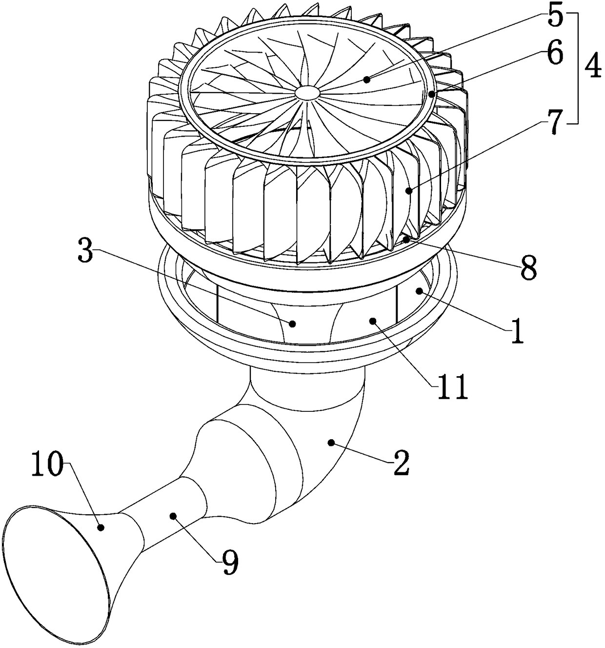
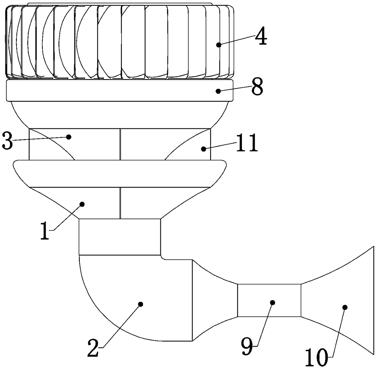
[0029] Embodiment 1, the present invention is a breeze energy gathering device suitable for breeze power generation, which is characterized in that it includes a trumpet-shaped lateral wind gathering port 1 with one end open, and the lateral wind gathering port 1 is set in the shape of a trumpet with a large upper end diameter to facilitate breeze The other end of the lateral air gathering port 1 is fixedly connected with a negative pressure chamber 2, and the negative pressure chamber 2 communicates with an external wind power generation device, and the negative pressure chamber 2 is formed in it by the function of the subsequent structure. The negative pressure makes the external breeze and air form a wind flow under the action of the atmospheric pressure difference, and enters the negative pressure chamber 2 through the side air gathering port 1 and drives the wind power generation device to generate electric energy. The wind power generation device needs to be connected with...
Embodiment 2
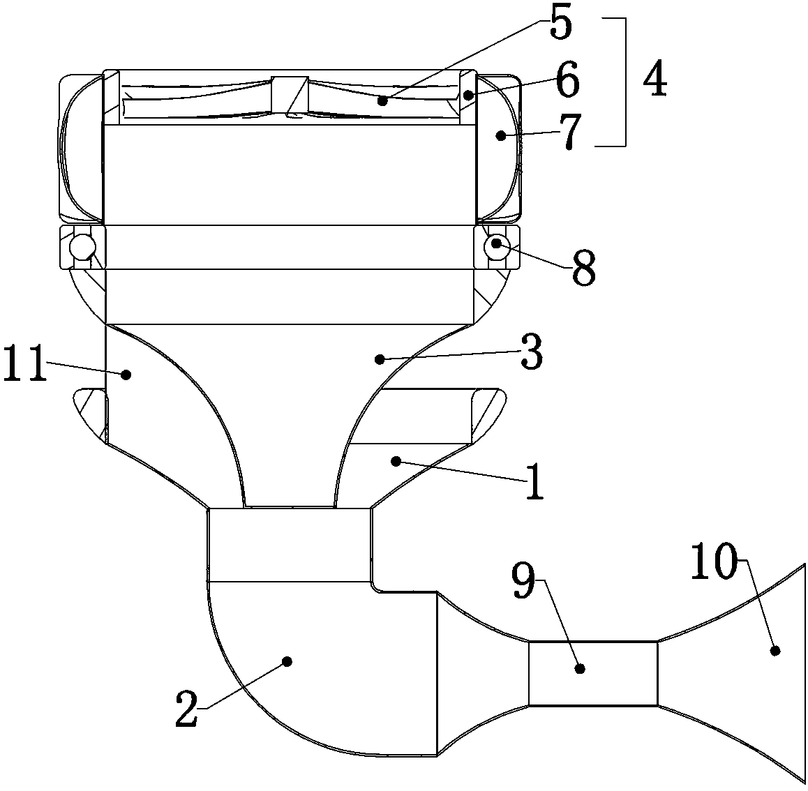
[0030] Embodiment 2. On the basis of Embodiment 1, common turbocharging devices include complex mechanical structures such as compressors, diffusers, and turbine groups. This device needs to use the wind power of the breeze itself to complete the supercharging, and the wind power of the breeze Limited, unable to generate excessive driving force, so this device needs to simplify the existing turbocharging device, so that it can effectively convert the limited breeze wind force into the power of the turbocharging device, so as not to consume the driving force of the breeze In the transmission between the internal mechanical structures, this embodiment provides a specific simplified method to achieve this effect. Specifically, the turbocharger 4 includes a hollow tube that is rotatably connected to the open end of the upper air collection port 3. Turbine shell 6, the outer wall of the turbine shell 6 is uniformly fixedly connected with a number of breeze blades 7, and the interior...
Embodiment 3
[0031] Embodiment 3. On the basis of Embodiment 2, the turbocharger 4 described in Embodiment 1 is rotatably connected to the opening end of the upper air collection port 3. Various methods can be used for the rotatable connection. This embodiment For example, a rotational connection method is provided so that the turbocharger 4 can be rotatably connected to the open end of the upper air collection port 3 with low loss. Specifically, the open end of the upper air collection port 3 is fixedly connected with a cylinder The roller bearing 8, the inner ring of the cylindrical roller bearing 8 is detachably connected to the turbine shell 6, specifically, the open end 3 of the upper air collecting port 3 is fixedly connected to the outer ring of the cylindrical roller bearing 8, The turbine shell 6 is detachably connected to the inner ring of the cylindrical roller bearing 8. In actual experimental use, it is found that the turbine shell 6 is connected to the inner ring of the cylind...
PUM
 Abstract
Description
Claims
Application Information
 - R&D Engineer
- R&D Manager
- IP Professional
- Industry Leading Data Capabilities
- Powerful AI technology
- Patent DNA Extraction
Browse by: Latest US Patents, China's latest patents, Technical Efficacy Thesaurus, Application Domain, Technology Topic.
© 2024 PatSnap. All rights reserved.Legal|Privacy policy|Modern Slavery Act Transparency Statement|Sitemap