Eureka AIR delivers breakthrough ideas for toughest innovation challenges, trusted by R&D personnel around the world.

A self-sustained synergistic reaction tank for photocatalysis conversion of pollutants and CO2 and a preparing method thereof

A technology of synergistic reaction and pollutants, applied in the direction of ion exchange water/sewage treatment, sterilization/microdynamic water/sewage treatment, energy wastewater treatment, etc., can solve the problems of imperfection, consumption of additional energy, high operating cost, etc., to achieve Eliminate the impact on the environment, promote conversion and power generation, and have a large effect on environmental pollution

Inactive Publication Date: 2015-05-13
SICHUAN UNIV
View PDF8 Cites 6 Cited by
  • Summary
  • Abstract
  • Description
  • Claims
  • Application Information

AI Technical Summary

Problems solved by technology

However, the current photocatalytic conversion of CO 2 The report on the coupling technology with photocatalytic degradation of organic pollutants is very incomplete, and an external bias voltage is still required to promote the reaction, which consumes external energy. There is no self-sustaining continuous working technology that only relies on solar energy to combine the reaction process and characteristics of the two, and the operating cost high

Method used

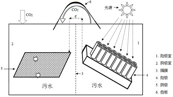

Image

  • A self-sustained synergistic reaction tank for photocatalysis conversion of pollutants and CO2 and a preparing method thereof
  • A self-sustained synergistic reaction tank for photocatalysis conversion of pollutants and CO2 and a preparing method thereof
  • A self-sustained synergistic reaction tank for photocatalysis conversion of pollutants and CO2 and a preparing method thereof

Examples


Embodiment 1

[0023] TiO2 with a tube diameter of 10-30 nm and a tube length of 20-30 μm was used 2 The nano-array tube is a photoelectrocatalytic material and acts as an anode. Put it obliquely into a phenol solution with a concentration of 0.1-5 mol / L to form an anode chamber. The inclination angle between the array tube and the horizontal plane is 50-60°. Add NaOH to the anode chamber Adjust the pH value of the solution, use Nafion117 cation exchange membrane as the diaphragm, and add saturated Na to the cathode chamber 2 CO 3 solution, the copper mesh as the cathode, and the anode as TiO 2 The distance between the array tube and the cathode copper grid is less than 30 cm, and the CO 2 Close to the cathode through the gas distribution plate, add a certain amount of 500 ~ 3000 m 2 / g of porous carbon enhanced CO 2 Absorption and dissolution, the transfer process is enhanced by stirring in the two chambers, and the anode TiO 2 The array tube is connected to the cathode copper grid to ...

Embodiment 2

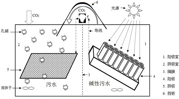
[0025] MoS with a particle size of 5–20 nm was impregnated 2 The powder is carried on the porous molecular sieve Ti—MCM-41, put into a titanium basket with quartz glass on one side as photocatalyst and anode, and put it obliquely into the printing and dyeing waste liquid to form the anode chamber, the quartz glass surface of the titanium basket and the The inclination angle of the horizontal plane is 10-60°. Add CaO to the anode chamber to adjust the pH value of the solution to be greater than 9. Anion exchange membranes are used as the diaphragm. Seawater is added to the cathode chamber, and graphite felt doped with Fe-doped nano-GaP is used as the cathode. 2 into the bottom of the cathode chamber, add 1000 ~ 2000 m 2 / g of porous carbon enhanced CO 2 The anode titanium basket and the cathode graphite felt are connected by wires to form an external circuit, the distance between the anode and the cathode is less than 50 cm, the load is a small fan, and a curved arc-shaped baf...

Embodiment 3

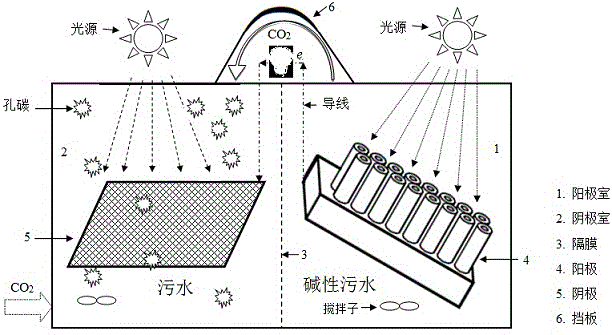
[0027] to the above Example 2 Simultaneously apply 100 ~ 200 W simulated sunlight to accelerate CO in the cathode chamber 2 conversion, such as image 3 Shown, add appropriate amount of NH to the cathode chamber 3 ·H 2 O consumes the photogenerated holes generated in the chamber, reduces the recombination of photogenerated holes and electrons, and strengthens the CO 2 For the electron reception of the electrode, the printing and dyeing waste liquid in the anode chamber is replaced with electroplating wastewater, and the other things remain unchanged. After adjusting the composition, concentration and pH value of the solutions on both sides, the composition of the cathode chamber product can be changed, which is formed by methane, CO, methanol, and formaldehyde.


PUM


Abstract

The invention relates to a self-sustained synergistic reaction tank for continuous photocatalysis conversion of pollutants and CO2 and a preparing method thereof, and belongs to the fields of environment protection, new energy and related fields. According to the reaction tank and the method, waste is treated and CO2 is converted synergistically by solar energy to generate electricity and prepare high-value chemical products. The technical problem to be overcome by the reaction tank and the method is to convert CO2 and pollutants only by solar energy and to improve social and economic benefit for pollutant treatment. According to a technical scheme, a photo-anode is adopted to oxidize and degrade the pollutants in an anode chamber, electrons generated in the oxidation process are utilized to promote CO2 conversion in a cathode chamber, the anode chamber and the cathode chamber are separated by a separating membrane, and the chemical potential difference between the two chambers is adjusted by controlling solutions in the anode chamber and the cathode chamber to allow the potential difference to make up insufficient of photovoltage and to meet energy requirements for running of the synergistic reaction tank, thus achieving self-sustained continuous running. According to the synergistic reaction tank and the method, the photocatalytic reaction efficiency in the anode chamber is high, the structure is simple, operability is high, and the synergistic reaction tank and the method are suitable for occasions where pollutants and CO2 are subjected to light coupling treatment for a long term.

Description

technical field [0001] The invention discloses a novel self-sustaining photocatalytic conversion of pollutants and CO 2 The synergistic reaction pool and its preparation method utilize clean solar energy alone to dispose of waste and synergistically generate electricity and produce high-value-added chemical products without additional energy, and belong to the fields of environmental protection, new energy and related fields. Background technique [0002] Greenhouse gas CO 2 The organic pollutants in sewage and sewage seriously threaten the survival and reproduction of human beings and the sustainable development of social economy, and even cause extreme climate phenomena, which has attracted great attention from all countries in the world. Many industrial processes (such as: printing and dyeing, photography, pesticides, explosives, disinfectants, lubricants, petrochemicals, rubber, plastics, etc.) will produce a large amount of waste liquid containing phenols, and toxic ...

Claims


Application Information

Patent Timeline
IPC IPC(8): C02F1/467C02F1/42
CPCY02W10/37
Inventor 王贵欣闫康平钟宜霏薛娱静
Owner SICHUAN UNIV
Why Eureka
Eureka Blog
Learn More