Variable frequency air conditioner

A frequency conversion air conditioner and sliding connection technology, applied in the field of frequency conversion air conditioners, can solve problems such as unexpected power failure, poor stability of frequency conversion air conditioners, hidden safety hazards, etc., and achieve the effect of preventing electric shock accidents

Inactive Publication Date: 2018-11-02
泉州市力松消防科技有限公司
5 Cites 0 Cited by

AI-Extracted Technical Summary

Problems solved by technology

[0002] With the continuous improvement of people's living standards, the use of inverter air conditioners in modern home life is also increasing. Inverter air conditioners need to be connected to the mains when they are used, but the pow...

Abstract

The invention discloses a variable frequency air conditioner which comprises a bayonet socket and a connecting plug connected with an air conditioner; the bayonet socket is internally provided with aconcave connecting groove of which the port faces rightwards; the inner wall of the left side of the concave connecting groove is provided with first conductive grooves; the parts, in the upper side and the lower side of the concave connecting groove, of the end surface on the right side of the bayonet socket are symmetrically provided with insertion grooves of which the ports face rightwards; theinner wall, close to the concave connecting groove, of the plug-in groove is provided with a first adapting cavity in a communicating manner; a first toothed connection wheel is rotatably arranged inthe first adapting cavity through a first adapting shaft; a bevel gear ring is arranged on the end surface on the front side of the first toothed connection wheel; and the parts, in the upper part and the lower part of the left side of the first adapting cavity, of the bayonet socket are symmetrically provided with first sliding grooves extending left and right.

Application Domain

Mechanical apparatusLighting and heating apparatus +2

Technology Topic

EngineeringBevel gear

Image

  • Variable frequency air conditioner
  • Variable frequency air conditioner

Examples

  • Experimental program(1)

Example Embodiment

[0020] All the features disclosed in this specification, or all disclosed methods or steps in the process, except for mutually exclusive features and/or steps, can be combined in any manner.
[0021] Any feature disclosed in this specification (including any appended claims, abstract and drawings), unless specifically stated, can be replaced by other equivalent or alternative features with similar purposes. That is, unless otherwise stated, each feature is just one example of a series of equivalent or similar features.
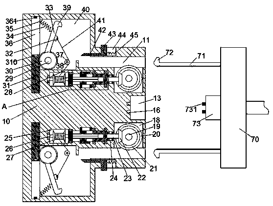
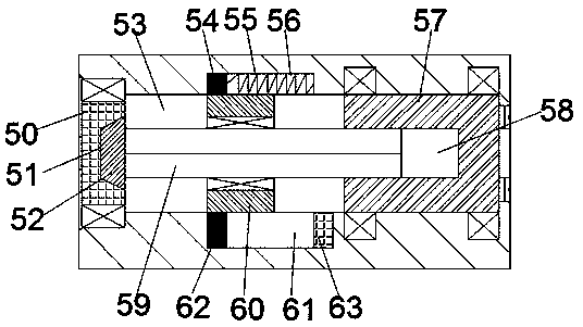
[0022] Such as Figure 1-2 As shown, an inverter air conditioner of the device of the present invention includes a socket 10 and a socket 70 connected to the air conditioner. The socket 10 is provided with a concave groove 13 with a rightward opening. The inner wall on the left side of the connecting groove 13 is provided with a first conductive groove 16, and the right end surface of the socket 10 is located at the upper and lower sides of the concave connecting groove 13 symmetrically provided with an inserting groove 11 with a right opening. A first adapter cavity 18 is provided in the inner wall of the groove 11 close to the recessed groove 13, and a first gear wheel 20 is rotatably provided in the first adapter cavity 18 through a first adapter shaft 19, The front end surface of the first gear wheel 20 is provided with a bevel gear ring 21, and the socket 10 is provided with a first sliding groove 53 extending left and right symmetrically on the left side of the first adapter cavity 18 A first connecting groove 24 is provided between the first sliding groove 53 and the first adapter cavity 18, and a second adapter shaft 23 is rotatably installed in the first connecting groove 24, The right end of the second adapter shaft 23 extends into the first adapter cavity 18, and the right tail part is fixedly provided with a bevel wheel 22 matingly connected with the bevel gear ring 21, and the first sliding groove 53. A spline sleeve 57 is rotatably installed in the upper and lower end walls of the right side through a bearing. The left end of the second adapter shaft 23 extends into the first sliding groove 53 and is connected to the spline sleeve 57. The side end surfaces are fixedly connected, the first sliding connection groove 53 is slidingly mounted with a first sliding connection block 60 located on the left side of the spline sleeve 57, and the first sliding connection block 60 passes through a bearing A spline shaft 59 extending left and right is rotatably installed. The spline sleeve 57 is provided with a spline groove 58 with a left opening. The right side of the spline shaft 59 extends into the spline groove 58 The first sliding groove 53 is provided with a second adapter cavity 25 in the inner wall of the left side of the first sliding groove 53, and the first sliding groove 53 and the second adapter cavity 25 are rotatably fitted and installed There is an adapter sleeve 50, the adapter sleeve 50 is provided with a locking groove 51 with a rightward opening, and the left side extension end of the spline shaft 59 is fixedly provided with a locking block extending into the locking groove 51 52. The left end of the adapter sleeve 50 is fixedly provided with a third adapter shaft 26 extending into the second adapter cavity 25, and the left end of the third adapter shaft 26 is connected to the second adapter shaft 26. The inner wall of the left side of the connecting cavity 25 rotates and fits and connects, the third adapter shaft 26 is fixedly provided with a winding barrel 27 located in the second adapter cavity 25, and a connecting rope 41 is provided on the winding barrel 27. A receiving groove 40 is provided in the inner wall of the inserting groove 11 in communication with each other, and a fourth adapter shaft 29 is rotatably provided between the front and rear inner walls of the left bottom of the receiving groove 40, and the fourth adapter shaft 29 A second gear wheel 30 is fixed on the upper part, a locking rod 33 is fixed on the second gear wheel 30, and an end of the locking rod 33 away from the second gear wheel 30 is fixedly provided with a lock joint 39. The left end surface of the plug connector 70 is symmetrically provided with a plug rod 71 matching with the plug groove 11, and the left end surface of the plug connector 70 between the upper and lower two plug rods 71 ​​is fixed. A plug-in block 73 matching the concave groove 13 is provided.
[0023] Beneficially or exemplarily, wherein the left end surface of the plug connector 70 is fixedly provided with a protruding block 72 that cooperates with the lock connector 39, and the inner end surface of the plug connector 70 is fixedly provided with the first tooth The first toothed bar with which the connecting wheel 20 is matched.
[0024] Beneficially or exemplarily, a guide groove 56 is provided in the end wall of the first sliding groove 53 close to the insertion groove 11, and the guide groove 56 is slidably installed with the first A guide block 54 fixedly connected to a sliding block 60, a first elastic member 55 that abuts the guide block 54 is provided in the inner wall of the right side of the guide groove 56, and the first sliding groove 53 is close to the The end wall of the insertion groove 11 is provided with a sliding contact hole 61, and a permanent magnet 62 fixedly connected to the first sliding block 60 is slidingly mounted in the sliding contact hole 61. An electromagnetic driving device 63 matched with the permanent magnet 62 is provided on the side inner wall.
[0025] Beneficially or illustratively, a second connecting groove 28 is provided in communication between the receiving groove 40 and the second adapter cavity 25, and the receiving groove 40 is far away from the second adapter cavity 25. An attachment block 35 is fixed on the end wall, the attachment block 35 is provided with a tension spring 34 fixedly connected to the outer end surface of the locking rod 33, and the inner end surface of the locking rod 33 is fixedly provided with a connecting arm 32 A fifth adapter shaft 38 located on the right side of the fourth adapter shaft 29 is rotatably installed between the front and rear inner walls of the receiving groove 40, and a fixed pulley 37 is fixed on the fifth adapter shaft 38, so The end of the connecting rope 41 far away from the winding barrel 27 passes through the fixed pulley 37 and is fixedly connected to the connecting arm 32.
[0026] Beneficially or illustratively, a second sliding groove 36 is elongated up and down on the left side inner wall of the receiving groove 40, and a second sliding joint block 31 is slidingly installed in the second sliding groove 36, The inner end surface of the second sliding contact block 31 is provided with a second toothed bar matingly connected to the second toothed wheel 30, and the second sliding contact block 31 is in an end surface away from the second adapter cavity 25 A second conductive groove 310 electrically connected to the first conductive groove 16 is provided, and an end wall of the second sliding groove 36 opposite to the second conductive groove 310 is provided with a power supply piece 361 connected to the mains .
[0027] Beneficially or illustratively, a conductive sheet 731 is provided on the left end surface of the plug-in block 73.
[0028] Beneficially or illustratively, wherein the end wall of the insertion groove 11 away from the first adapter cavity 18 is provided with a third sliding groove 44 communicating with the outside, and the third sliding groove 44 is left The side inner wall is provided with a fourth sliding connection groove communicating with the receiving groove 40, a third sliding connection block 43 is slidingly installed in the third sliding connection groove 44, and the right end surface of the third sliding connection block 43 A second elastic member 45 fixedly connected to the inner wall of the right side of the third sliding connection groove 44 is provided. The fourth sliding connection groove is slidably installed with a fixed connection to the left end surface of the third sliding connection block 43 The fourth sliding block 42 is fixedly provided with a bevel block extending into the receiving groove 40 at the left end of the fourth sliding block 42.
[0029] In the device of the present invention, when the socket 10 is in the initial state, the locking block 52 is inserted into the locking groove 51 under the action of the first elastic member 55 and is locked and connected. The locking connector 39 is stretched away from the insertion groove 11, and at the same time, driven by the second gear wheel 30, the second sliding contact block 31 is away from the end surface of the second conductive groove 310 and the The end wall of the second sliding groove 36 away from the power supply sheet 361 abuts against, and the second conductive groove 310 is relatively far away from the power supply sheet 361, the first conductive groove 16 is not charged, and the second conductive groove Under the action of the elastic member 45, the left end surface of the third sliding connection block 43 abuts against the left end surface of the third sliding connection groove 44, and the bevel block extends into the receiving groove 40.
[0030] When in use, align the plug rod 71 and the plug block 73 with the plug groove 11 and the concave groove 13 respectively, and then push the plug connector 70 to the left to make the plug rod 71 is inserted into the insertion slot 11 and slid to the left. During the sliding of the insertion rod 71 to the left, the first toothed wheel 20 can be driven to rotate through the first toothed bar. After the connecting wheel 20 rotates, the bevel wheel 22 can be driven by the bevel gear ring 21 to drive the second adapter shaft 23 and the spline sleeve 57 to rotate, and the spline sleeve 57 can pass through the flower after rotating. The key shaft 59 drives the adapter sleeve 50 and the winding barrel 27 to rotate. After the winding barrel 27 rotates, the locking rod 33 can be pulled through the connecting rope 41 to drive the locking joint 39 toward When the insertion groove 11 rotates, the locking rod 33 can be driven by the second gear wheel 30 to move the second sliding contact block 31 outward during the rotation process, and the locking joint 39 can be rotated during the rotation process. The fourth sliding contact block is actuated by the bevel block to push the third sliding contact block 43 to slide to the right. When the right end surface of the plug connector 70 abuts the left end surface of the plug 10, the plug The left end surface of the connecting block 73 abuts against the left inner wall of the concave connecting groove 13, the conductive sheet 731 is inserted into the first conductive groove 16, the locking connector 39 abuts against the convex block 72, and the first The three sliding block 43 pushes the fourth sliding block under the action of the second elastic member 45 to drive the bevel block to be located in the receiving groove 40 again, and the inner end surface of the bevel block is in contact with the The outer end surface of the locking rod 33 is pressed against, so that the plug connector 70 is locked on the socket 10, and at the same time, the power supply piece 361 is completely inserted into the second conductive groove 310, and the first A conductive slot 16 is energized to make the air conditioner run;
[0031] After the use is completed, pull the third sliding block 43 to make the bevel block exit the receiving slot 40, and then control the electromagnetic drive device 63 to be powered on. The electromagnetic drive device 63 can act on The permanent magnet 62 slides the first sliding block 60 to the right, so that the locking block 52 is separated from the locking groove 51. After the locking block 52 is separated from the locking groove 51, The socket 10 is restored to the initial state under the action of the tension spring 34, and finally the socket 70 is pulled out to the right.
[0032] The beneficial effects of the present invention are:
[0033] In the device of the present invention, when the socket is in the initial state, the locking block is inserted into the locking groove and locked and connected under the action of the first elastic member, and under the tension of the tension spring, the The lock connector is away from the insertion groove, and at the same time, driven by the second gear wheel, the end surface of the second sliding block away from the second conductive groove and the second sliding groove away from the power supply The end surface walls of the sheet are opposed to each other, and the second conductive groove is relatively far away from the power supply sheet, and the first conductive groove is not charged, so that electric shock accidents can be prevented and the safety of electricity use can be improved.
[0034] When in use, align the plug rod and the plug block with the plug groove and the concave groove respectively, and then push the plug connector to the left to insert the plug rod into the plug In the slot and slide to the left, the first toothed bar can drive the first toothed wheel to rotate during the sliding of the plug rod to the left, and the first toothed wheel can pass through the cone after rotating. The gear ring drives the bevel wheel to drive the second adapter shaft and the spline sleeve to rotate. After the spline sleeve rotates, the spline shaft can drive the adapter sleeve and the winding barrel to rotate After the winding cylinder is rotated, the locking rod can be pulled through the connecting rope to drive the locking joint to rotate toward the insertion groove, and the locking rod can pass through the second The gear wheel drives the second sliding contact block to move outwards. During the rotation of the lock joint, the fourth sliding contact block can be actuated by the bevel block to push the third sliding contact block to slide to the right. When the right end surface of the plug connector abuts against the left end surface of the plug, the left end surface of the plug block abuts against the inner wall of the left side of the concave groove, and the conductive sheet is inserted into the first conductive groove. The lock joint abuts against the protruding top block, and the third sliding block pushes the fourth sliding block under the action of the second elastic member to drive the bevel block to be located in the receiving groove again, And the inner end surface of the bevel block is pressed against the outer end surface of the locking rod, so that the plug connector is locked on the plug socket, which can prevent the plug from loosening and improve the stability of the power supply connection;
[0035] At the same time, the power supply sheet is completely inserted into the second conductive slot, and the first conductive slot is energized to make the air conditioner run;
[0036] After the use is completed, pull the third sliding block to make the bevel block exit the receiving groove, and then control the electromagnetic drive device to be powered on, and the electromagnetic drive device can act on the permanent magnet after being powered on The first sliding block is slid to the right to disengage the locking block from the locking groove. After the locking block is disengaged from the locking groove, the plug is inserted under the action of the tension spring The socket returns to the initial state, and finally the plug connector is pulled out to the right.
[0037] The device of the invention has a simple structure and simple operation, which can greatly improve the stability and safety of the air conditioner during power supply connection.
[0038] The above shows and describes the basic principles, main features and advantages of the present invention. Those skilled in the industry should understand that the present invention is not limited by the above-mentioned embodiments. The above-mentioned embodiments and the specification describe only the principles of the present invention. Without departing from the spirit and scope of the present invention, the present invention will have various aspects. Various changes and improvements, these changes and improvements all fall into the claimed invention. The scope of protection claimed by the present invention is defined by the appended claims and their equivalents.

PUM

no PUM

Description & Claims & Application Information

We can also present the details of the Description, Claims and Application information to help users get a comprehensive understanding of the technical details of the patent, such as background art, summary of invention, brief description of drawings, description of embodiments, and other original content. On the other hand, users can also determine the specific scope of protection of the technology through the list of claims; as well as understand the changes in the life cycle of the technology with the presentation of the patent timeline. Login to view more.

Similar technology patents

Efficient traditional Chinese medicine extractor

InactiveCN108836857AAvoid Electric Shock Accidents
Owner:佛山启辰环保资源再生有限公司

Public mobile phone charging station

Owner:南宁市益诚安防设备有限公司

An advanced multifaceted detector

Owner:广州迪然安全检测技术有限公司

Automatic film sticking machine

Owner:广州创码信息科技有限公司

Classification and recommendation of technical efficacy words

  • Avoid Electric Shock Accidents

Automatic power plug connection system

Owner:河源联禾电力规划设计有限公司

LED luminaire device for factory lighting

InactiveCN109595495AAvoid Electric Shock AccidentsSafety during installation
Owner:蒋懿

Improved oil smoke purification device

InactiveCN107317197AAvoid Electric Shock AccidentsImprove mating stability and accuracy
Owner:温岭市兴庆机械设备有限公司

Router with air purifier

Owner:XIAN ZHISHIXIN ELECTRONICS TECH
Why Eureka
Try Eureka