Rigging placing rack for large equipment hoisting

A technology for large-scale equipment and racks, applied in packaging and internal accessories, etc., can solve problems affecting rigging assembly, affecting hoisting time, hidden dangers, etc., to reduce hoisting time, reduce use risks, and prevent hoisting accidents Effect

Pending Publication Date: 2018-11-09
江苏华滋能源工程有限公司
View PDF5 Cites 0 Cited by
  • Summary
  • Abstract
  • Description
  • Claims
  • Application Information

AI Technical Summary

Problems solved by technology

[0004] The technical problem to be solved by the present invention is to overcome the defects of the prior art and provide a rigging rack for hoisting large-scale equipment, which can effectively solve the above-mentioned problem that there is no clear storage equipment for hoisting rigging on the market. When the rigging is not in use, it is generally placed together, which will make the rigging entangled together, and it will be very cumbersome to take it out again, and it will cause the rigging to rub against each other for a long time, which will damage the rigging , so that there will be safety hazards when using this type of rigging, and it will also affect the assembly of the rigging, affecting technical problems such as hoisting time

Method used


Image

  • Rigging placing rack for large equipment hoisting
  • Rigging placing rack for large equipment hoisting

Examples


Embodiment

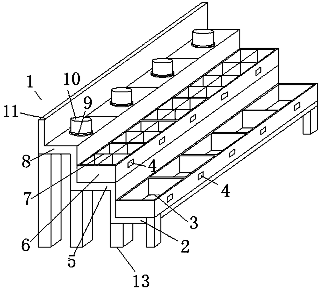
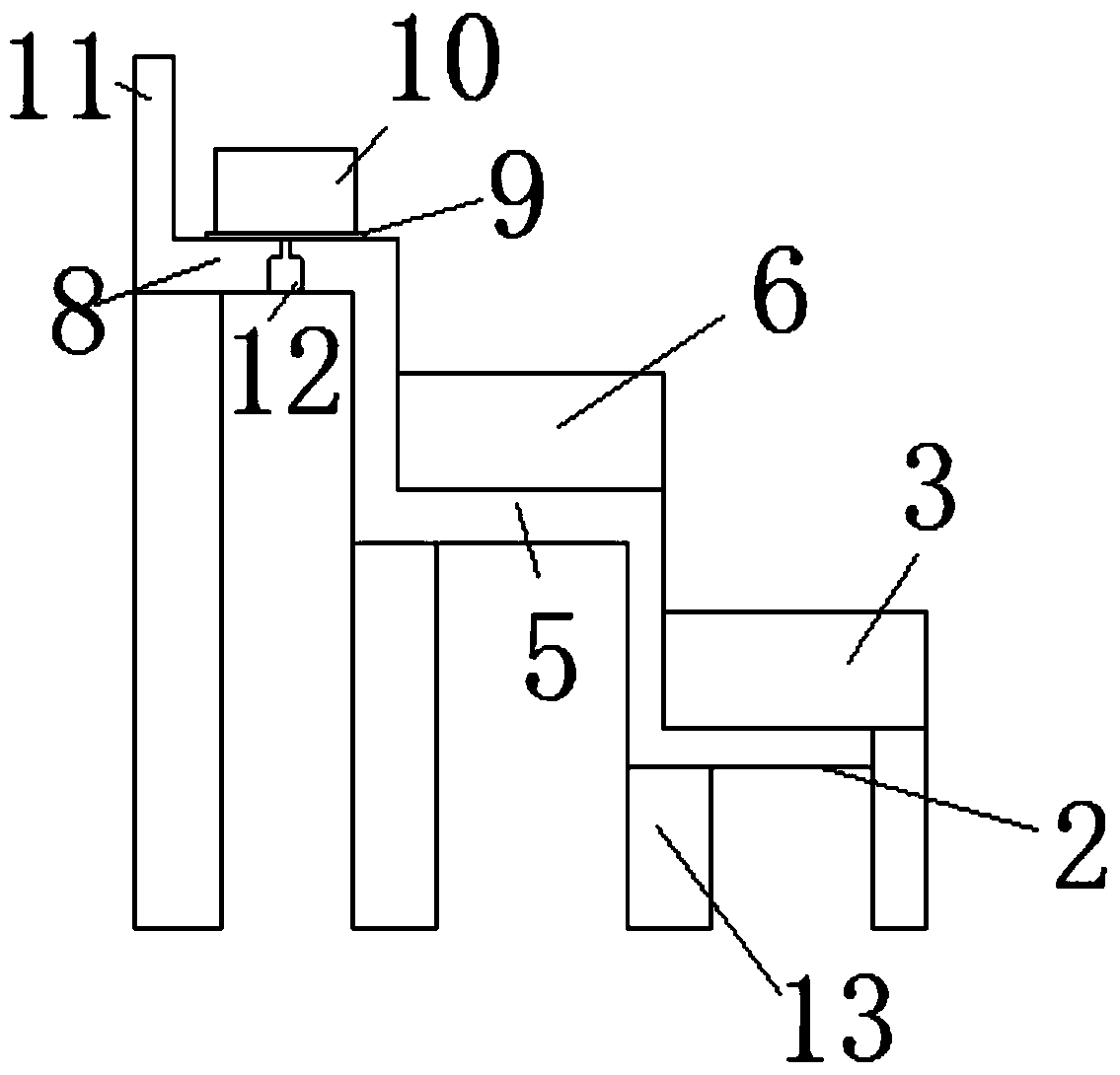
[0018] Such as Figure 1-2 As shown, the rigging rack for large-scale equipment hoisting includes a rack body 1, which includes a first level 2, and a number of storage boxes 3 are connected to the first level 2, and the front side of the storage box 3 is connected There is a nameplate 4, the second level 5 is connected to the upper edge of the first level 2 back plate, the shackle storage box 6 is connected to the second level 5, the shackle storage box 6 is equipped with a partition plate 7, and the second level 5 back A third level 8 is connected to the upper edge of the board and a turntable 9 is connected to the upper side of the turntable 9 is connected to a winding column 10, the rear end of the third level 8 is connected to a rear baffle 11, and a number of motors 12 are provided in the third level 8. The bottom ends of the first tier 2, the second tier 5 and the third tier 8 are all connected with a supporting column 13 and the output end of the motor 12 is connected w...


PUM


Abstract

The invention discloses a rigging placing rack for large equipment hoisting. The rigging placing rack for large equipment hoisting comprises a placing rack body. The placing rack body comprises a first step layer, wherein a plurality of storage boxes are connected to the first step layer; a nameplate is connected to the front side of the storage boxes; a second step layer is connected to the upperedge of a back plate of the first step layer; a shackle storage box is connected to the second step layer; a partition plate is arranged in the shackle storage box; a third step layer is connected tothe upper edge of a back plate of the second step layer; a rotary disc is connected to the third step layer; a winding column is connected to the upper side of the rotary disc; and a back baffle plate is connected to the back end of the third step layer. The rigging placing rack for large equipment hoisting disclosed by the invention has the beneficial effects that the rigging placing rack for large equipment hoisting is divided into the first step layer, the second step layer and the third step layer, so that different rigging accessories can be stored in a classified manner; the storage boxes are fixedly connected to the first step layer, and lifting lugs for the rigging can be placed therein; and the storage boxes are connected to the first step layer, so that the different lifting lugs can be finely classified secondarily, and the name plate is connected to the front side of the storage boxes.

Description

Technical field [0001] The invention relates to a rigging rack, in particular to a rigging rack for hoisting large equipment, and belongs to the technical field of supporting equipment for hoisting devices. Background technique [0002] Nowadays, the transportation and installation of many large-scale equipment requires lifting devices to lift them for transportation and installation. When lifting some equipment, rigging is needed to fix the lifting equipment and connect it with the lifting equipment for lifting. When the equipment is hoisted, the rigging used varies greatly depending on the equipment being hoisted. When some rigging is not in use, it needs to be recycled and stored. [0003] There is no clear storage device for hoisting rigging on the market. Nowadays, rigging is usually placed together when not in use. This will make the rigging entangled, and it will be very difficult to use again. It is cumbersome, and the rigging will rub against each other for a long time to...

Claims


Application Information

Patent Timeline
Patent Type & Authority Applications(China)
IPC IPC(8): B65D25/04B65D25/02B65D85/00
CPCB65D25/02B65D25/04B65D85/00
Inventor 袁东东周兵张朝华王利江
Owner 江苏华滋能源工程有限公司
Why Eureka
Try Eureka