
Test device capable of determining shaft component anti-seize performance and application thereof

A test device and a technology for shaft parts, applied in the direction of mechanical bearing testing, etc., can solve the problem of difficulty in simulating the motion state and bearing form of shaft parts, and achieve the effect of accurate motion state and bearing form, simple structure and convenient use.

Active Publication Date: 2018-11-09
NANJING VOCATIONAL UNIV OF IND TECH
View PDF14 Cites 0 Cited by
  • Summary
  • Abstract
  • Description
  • Claims
  • Application Information

AI Technical Summary

Problems solved by technology

According to the relevant test standards, the coupling forms of the friction pair of the friction and wear test piece mainly include the "ring-block" type, "pin-disc" type and "four-ball" type, etc. It is difficult to simulate the motion state and load-bearing form of shaft parts

Method used


Image

  • Test device capable of determining shaft component anti-seize performance and application thereof
  • Test device capable of determining shaft component anti-seize performance and application thereof
  • Test device capable of determining shaft component anti-seize performance and application thereof

Examples


Embodiment 1

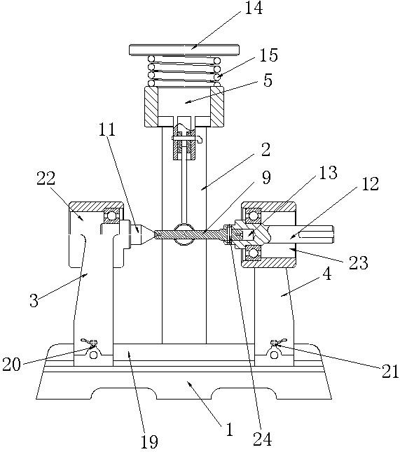
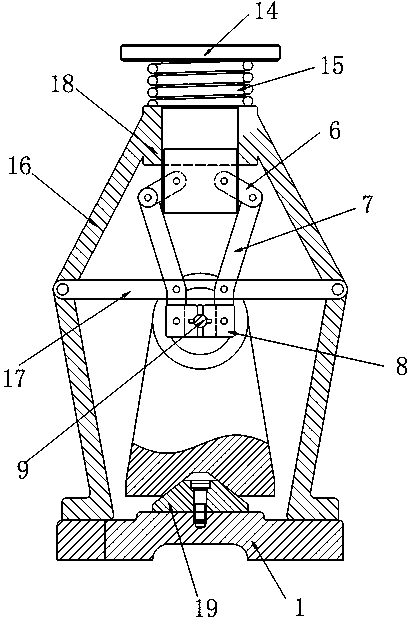
[0032] Such as figure 1 and figure 2 The test device that can measure the anti-jamming performance of shaft parts includes a workbench 1, a loading bracket 2 with a detachable bottom end installed on the workbench 1, which is set on the workbench 1 and forms a horizontal movement with the workbench 1. The first movable frame 3 and the second movable frame 4 of the pair and the loading piston 5 that are arranged on the top of the loading bracket 2 and the loading bracket 2 constitute a vertical movement pair, the first movable frame 3 and the second movable The racks 4 all slide along the direction perpendicular to the loading bracket 2 .

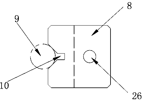
[0033] In the present application, two left and right connecting rods 6 are symmetrically rotated through a living hinge on both sides of the lower part of the loading piston 5, and one end of the two connecting rods 6 away from the loading piston 5 is respectively rotated through a living hinge to be provided with a loading lever 7. The ...

Embodiment 2

[0041] This embodiment is a method for measuring the seizure resistance of the test shaft using the test device described in Embodiment 1. The method of this embodiment specifically includes the following steps:

[0042] Step 1, move the first movable frame 3 towards the direction away from the second movable frame 4, install one end of the test shaft 9 to be tested in the mounting hole 13 on the transmission shaft 12, and keep the test shaft 9 through the Pass between the two clamping blocks 8, move the first movable frame 3, make the top 11 withstand the end of the test shaft 9 away from the end of the second movable frame 4, and paste the pressure sensor on the surface of the test shaft 9;

[0043] Step 2, preload the loading piston 5 to make it move downward, and remove the preload after the clamp block 8 can stably hold the test shaft 9 .

[0044] Step 2.1, manually rotate the transmission shaft 12, use a dial indicator to measure the runout of the test shaft 9 for one ro...

Embodiment 3

[0051] The technical solution of this embodiment is a method for measuring the ultimate seizure resistance of test shafts. The implementation of this embodiment adopts the test device disclosed in Embodiment 1 that can measure the seizure resistance of shaft parts. The method described in this embodiment is specific. Include the following steps:

[0052] Step 1, move the first movable frame 3 towards the direction away from the second movable frame 4, install one end of the test shaft 9 to be tested in the mounting hole 13 on the transmission shaft 12, and keep the test shaft 9 through the Pass between the two clamping blocks 8, move the first movable frame 3, make the top 11 withstand the end of the test shaft 9 away from the end of the second movable frame 4, and paste the pressure sensor on the test shaft 9 surface.

[0053] Step 2, preload the loading piston 5 to make it move downward, and remove the preload after the clamp block 8 can stably clamp the test shaft 9 .

[0...


PUM


Abstract

The invention discloses a test device capable of determining shaft component anti-seize performance and application thereof. The test device comprises a workbench, a loading support, a first flexiblerack, a second flexible rack and a loading piston. The two sides of the lower part of the loading piston are symmetrically and rotatably provided with connecting rods. One end, which is away from theloading piston of each connecting rod is rotatably provided with a loading lever. The lower part of the loading lever is rotatably connected with the loading support and the bottom end of each loadinglever is rotatably provided with a clamp block. The opposite surfaces of the clamp blocks are provided with V-shaped grooves matched with the test shaft. The first flexible rack is rotatably providedwith a tip. The second flexible rack is rotatably provided with a transmission shaft. The tip and the transmission shaft are arranged on the same horizontal line. One end, which is close to the tip,of the transmission shaft is provided with an installing hole used for installing the test shaft. The other end of the transmission shaft is used for being connected with a driving device for drivingthe transmission shaft to rotate. The beneficial effects of the test device are that the motion state and the bearing form of the shaft component can be accurately simulated and the anti-seize performance of the shaft component can be directly measured.

Description

technical field [0001] The invention relates to a test device capable of measuring the seizure resistance of shaft parts and its application. Background technique [0002] Occlusion, also known as welding, is one of the main forms of early failure of mechanical parts, and it is more harmful in engineering. The failure mechanism is that when the radial pressure of the friction pair is large enough, the locally raised parts on the contact surface will produce solid-phase welding due to plastic rheology and form adhesion points. Under relative sliding, when the adhesion point is sheared and disengaged under the action of shear stress, part of the metal is transferred from one surface to the other surface, thus forming a bite. Experimental studies have shown that the main factors affecting the anti-seize performance of mechanical parts include material, surface processing accuracy, heat treatment and surface treatment technology, and lubrication conditions between friction pair...

Claims


Application Information

Patent Timeline
Patent Type & Authority Applications(China)
IPC IPC(8): G01M13/04
CPCG01M13/04Y02E30/30
Inventor 张长英
Owner NANJING VOCATIONAL UNIV OF IND TECH
Learn More