Thermal ball valve resistant to leakage

A leak-proof and thermal technology, applied to the valve details, valve device, valve housing structure, etc., to achieve the effect of simple and practical structure, convenient operation and strong adaptability

Pending Publication Date: 2018-11-13
JIANGSU CHENGGONG VALVE TECH
View PDF0 Cites 1 Cited by
  • Summary
  • Abstract
  • Description
  • Claims
  • Application Information

AI Technical Summary

Problems solved by technology

[0003] The object of the present invention is to provide an anti-leakage thermal ball valve in order to solve the above problems, which solves the current existing problems

Method used


Image

  • Thermal ball valve resistant to leakage
  • Thermal ball valve resistant to leakage
  • Thermal ball valve resistant to leakage

Examples


Embodiment Construction

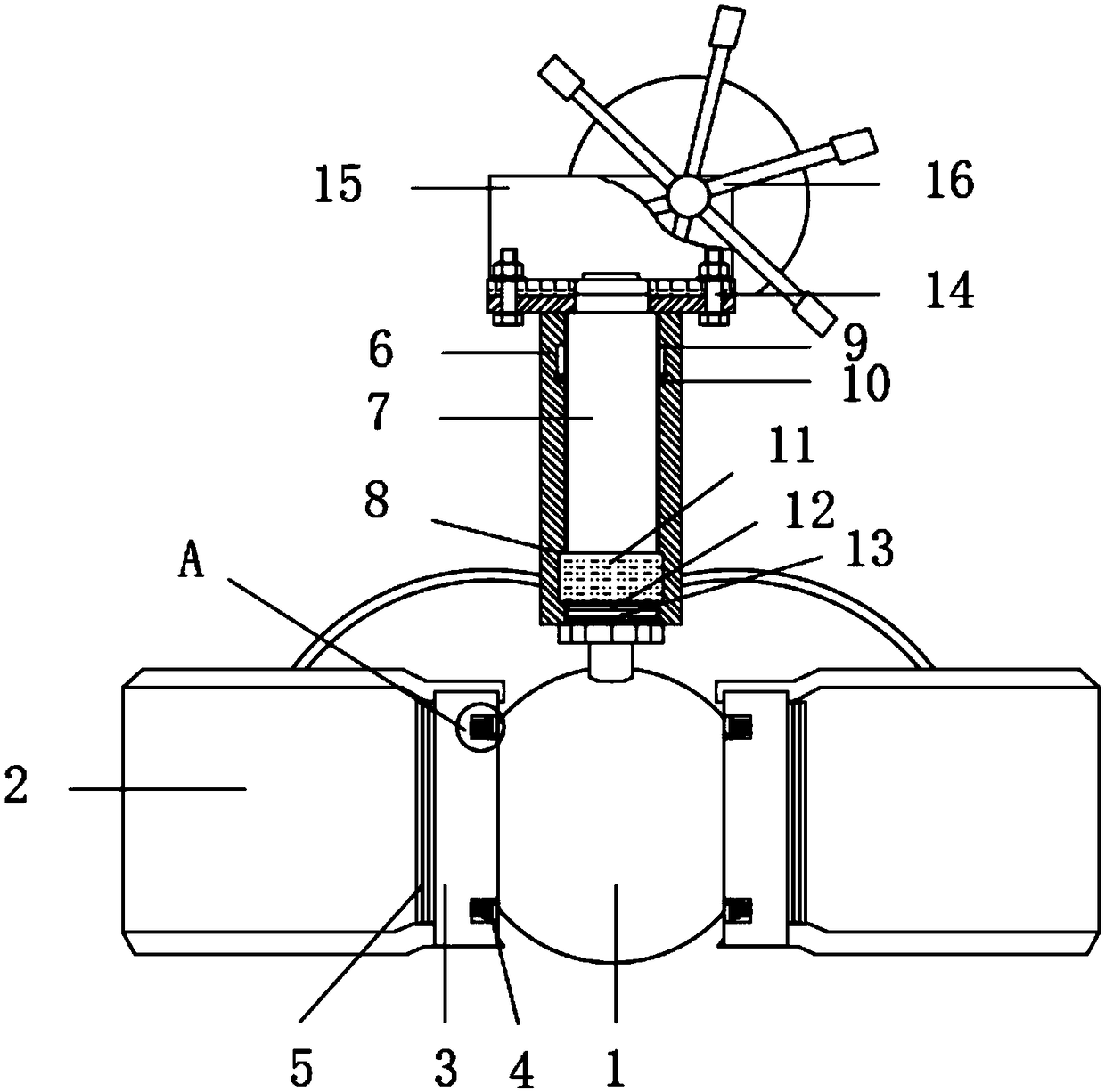
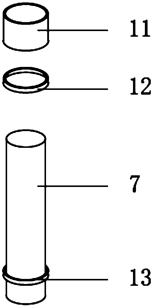
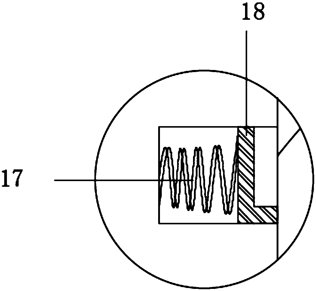
[0019] like Figure 1-3 As shown in the figure, this specific embodiment adopts the following technical solutions: an anti-leakage thermal ball valve, comprising a ball body 1, a floating valve seat 3 is connected on both sides of the ball body 1, and the floating valve seat 3 is close to one side of the ball body 1. Both ends are connected with a buffer limit mechanism 4, the buffer limit mechanism 4 is provided with a spring 17, the spring 17 is connected with the floating valve seat 3, and the other end of the spring 17 is connected with a contact block 18, the contact The side of the block 18 away from the spring 17 is connected with the ball 1, the spring 17 is connected with the ball 1 through the contact block 18, the side of the floating valve seat 3 away from the ball 1 is connected with the connecting pipe 2, the The connection between the floating valve seat 3 and the connecting pipe 2 is provided with a No. 1 sealing ring 5, the upper end of the ball 1 is provided ...


PUM


Abstract

The invention discloses a thermal ball valve resistant to leakage. The thermal ball valve resistant to leakage comprises a sphere. Floating valve seats are connected with the two sides of the sphere.Buffer limiting mechanisms are connected with both the upper end and the lower end of the side, close to the sphere, of each floating valve seat. According to the thermal ball valve resistant to leakage, a valve rod is made of 20Cr13 stainless steel, the valve rod is high in torsional strength and smooth in machined surface, and a lubricating sealing effect is improved; the valve rod is installedfrom the lower part of the interior of a valve rod connecting sleeve, pressure is pushed towards the valve rod by using a thrust washer support made of a low-friction material, and therefore the valverod only plays a role in transmitting torque without generating load; meanwhile, because the valve seats are composed of carbon fiber reinforced polytetrafluoroethylene and springs, self lubrication,friction resistance and resistance to temperature as high as 200 DEG C are achieved; an O-shaped sealing ring is made of VITON fluororubber, and thereby being good in temperature resistance, resistant to friction and high in corrosion resistance; and a first sealing ring is assembled at a low temperature, and thereby being high in adaptive capacity of changes of pressure and temperature, and no leakage is likely to happen within the marked range of pressure and temperature.

Description

technical field [0001] The invention belongs to the technical field of valves, in particular to an anti-leakage thermal ball valve. Background technique [0002] With the development of society, the rapid development of modern large-scale machinery, petroleum, chemical industry, new energy, nuclear industry and other industries, the requirements for valve sealing and safety and reliability are getting higher and higher. The thermal ball valve used in china is deficient in both stability and tightness, the service life is not long, and it is easy to damage and require maintenance. SUMMARY OF THE INVENTION [0003] The purpose of the present invention is to provide an anti-leakage thermal ball valve in order to solve the above problems, which solves the existing problems. [0004] In order to solve the above-mentioned problems, the present invention provides a kind of technical scheme: [0005] An anti-leakage thermal ball valve, comprising a sphere, a floating valve seat ...

Claims


Application Information

Patent Timeline
Patent Type & Authority Applications(China)
IPC IPC(8): F16K5/06F16K5/08F16K5/20F16K41/04F16K27/06
CPCF16K5/0647F16K5/0663F16K5/0694F16K5/08F16K5/201F16K27/067
Inventor 陈双河孙宁
Owner JIANGSU CHENGGONG VALVE TECH
Why Eureka
Try Eureka