Distributed beam capable of independently transmitting vertical loads at multiple points and its implementation method

A technology of vertical load and beam distribution, applied in the direction of analyzing materials, using stable tension/pressure testing materials, instruments, etc., it can solve the problems of inability to load components in different positions, and the force of components does not match, so as to achieve the implementation of operation. simple effect

Active Publication Date: 2020-06-23
CHINA UNIV OF MINING & TECH
View PDF7 Cites 0 Cited by
  • Summary
  • Abstract
  • Description
  • Claims
  • Application Information

AI Technical Summary

Problems solved by technology

The structure of the existing single distribution beam is usually I-beam or box-shaped, and the force transmission can only achieve uniform or multi-point uniform loading in the length direction of the distribution beam itself. The components usually distribute the force according to their own stiffness, which will cause the situation that the experimental loading does not match the force of the components in the actual engineering structure
[0004] Existing conventional distribution beams are unable to load components at different positions independently, and the stressed components in actual engineering are not truly uniform in many cases, so such components have no effect on the distribution during the loading test. The requirement of the beam changes from uniform load transfer to non-uniform transfer

Method used


Image

  • Distributed beam capable of independently transmitting vertical loads at multiple points and its implementation method
  • Distributed beam capable of independently transmitting vertical loads at multiple points and its implementation method
  • Distributed beam capable of independently transmitting vertical loads at multiple points and its implementation method

Examples


Embodiment approach

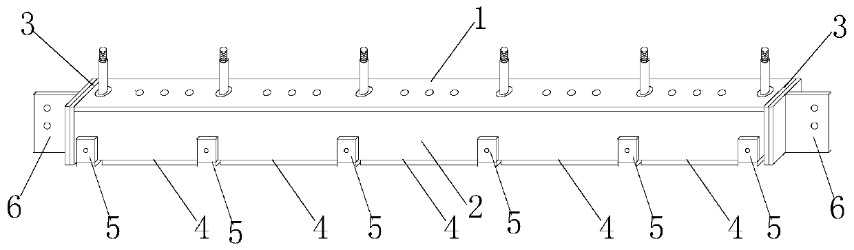
[0040] An implementation method of a distribution beam capable of independently transmitting vertical loads at multiple points and locally according to the present invention comprises the following steps:

[0041] Step 1. Using steel plates as raw materials, use stamping or welding processes to mass-produce open-hole box-shaped beams, U-shaped backing plates 5-1, force transmission screws 5-2, and T-shaped pieces 6;

[0042] Step 2, the length of the force transmission screw 5-2 is the same as that of the bottom backing plate 5-1-1. Figure 2d The short and medium threaded end 5-2-1) is connected with the bolt holes of the bottom backing plate of the independent partial load transfer member 5, and the assembled independent partial load transfer member 5 is placed in the gap between the bottom plates 4 of the open box-shaped body beams ;

[0043] Step 3. Before the experiment starts, pass the placed independent local load transfer member 5 and the open box beam through the sid...


PUM

PropertyMeasurementUnit
thicknessaaaaaaaaaa
heightaaaaaaaaaa

Abstract

The invention provides a distribution beam capable of realizing multi-point local independent transfer of vertical load. The distribution beam comprises a distribution beam body, wherein the distribution beam body mainly comprises a holed box beam, a plurality of independent local load transfer pieces and two T-shaped pieces by assembly; the plurality of independent local load transfer pieces arelocated at intervals of bottom plates of the bottom surface of the holed box beam; each independent local load transfer piece comprises a U-shaped base plate and a force transfer screw which are integrally connected by assembly; the independent local load transfer pieces are detachably connected with the holed box beam through the U-shaped base plates; the force transfer screws penetrate the holedbox beam and are connected with a loading device; the T-shaped pieces are located on two sides of the holed box beam; the holed box beam is connected with an external device through the T-shaped pieces. The distribution beam can perform multi-point local independent vertical loading besides the conventional functions such as constraint and uniform loading of the conventional distribution beam andcan realize independent vertical loading of each of multiple columns of walls, thereby effectively avoiding inconsistence of distributed force with actual force in loading experiment processes.

Description

technical field [0001] The invention relates to a distribution beam for loading experiments, in particular to a distribution beam capable of independently transmitting vertical loads at multiple points and locally and an implementation method thereof, belonging to the technical field of civil engineering. Background technique [0002] Loading experiment is an important experiment type in civil engineering experiment. Loading experiment can correctly simulate the stress state of specimen model in actual engineering structure, which is of great significance to the study of structures in civil engineering. A complete loading system usually consists of many different types of devices, and the distribution beam is often an indispensable device in a large number of loading experiments. [0003] On the one hand, the existing distribution beam can realize the restraint and fixation of the loaded specimen during the loading experiment process, and on the other hand, it can realize th...

Claims


Application Information

Patent Timeline
Patent Type & Authority Patents(China)
IPC IPC(8): G01N3/02G01N3/08
CPCG01N3/02G01N3/08G01N2203/0019
Inventor 陈伟王强叶继红赵庆阳
Owner CHINA UNIV OF MINING & TECH
Why Eureka
Try Eureka