
Water Conservancy Project Filtration Device

A filter device, water conservancy engineering technology, applied in the direction of filtration separation, moving filter element filter, separation method, etc., can solve the problem of difficult cleaning of impurities, etc., to achieve the effect of ingenious structure, strong practicability and novel concept

Active Publication Date: 2020-12-18
福建艺景生态建设集团有限公司
View PDF5 Cites 0 Cited by
  • Summary
  • Abstract
  • Description
  • Claims
  • Application Information

AI Technical Summary

Problems solved by technology

[0006] In view of the above situation, in order to overcome the defects of the prior art, the present invention provides a water conservancy project filter device, which effectively solves the problem that impurities are easy to be cleaned during the water conservancy water delivery process

Method used


Image

  • Water Conservancy Project Filtration Device
  • Water Conservancy Project Filtration Device

Examples


Embodiment Construction

[0014] The specific implementation manners of the present invention will be described in further detail below in conjunction with the accompanying drawings.

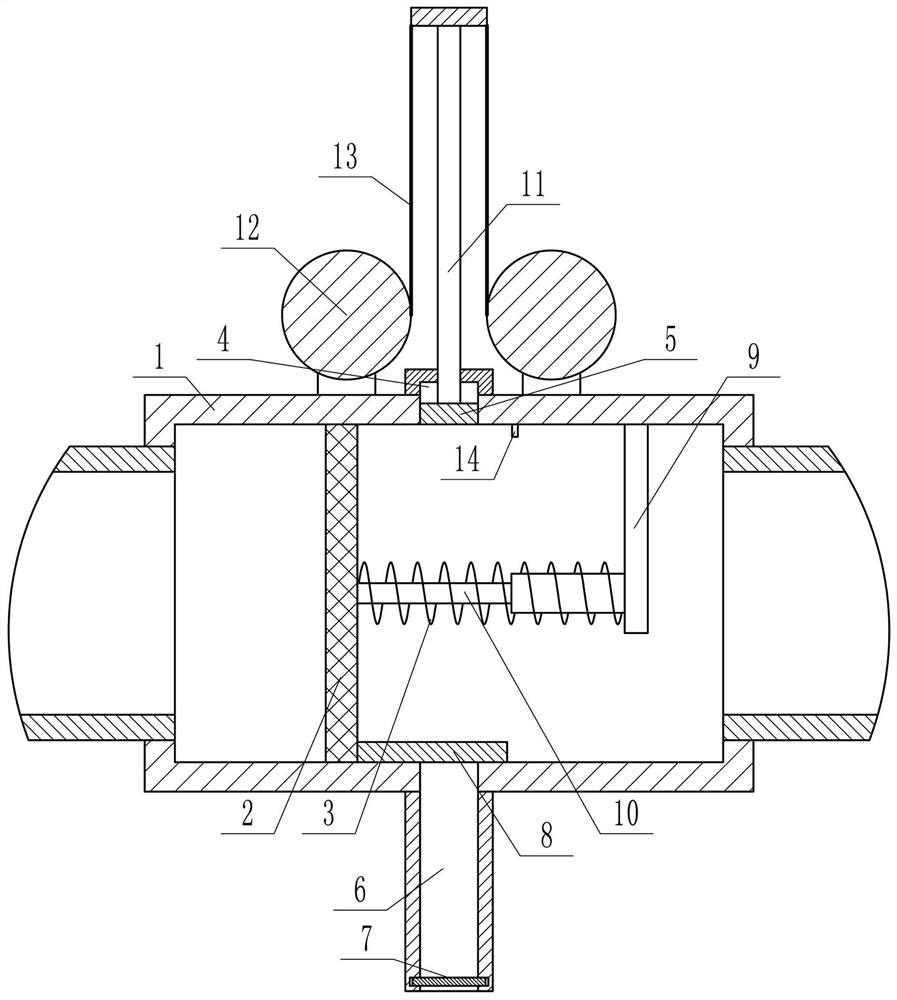
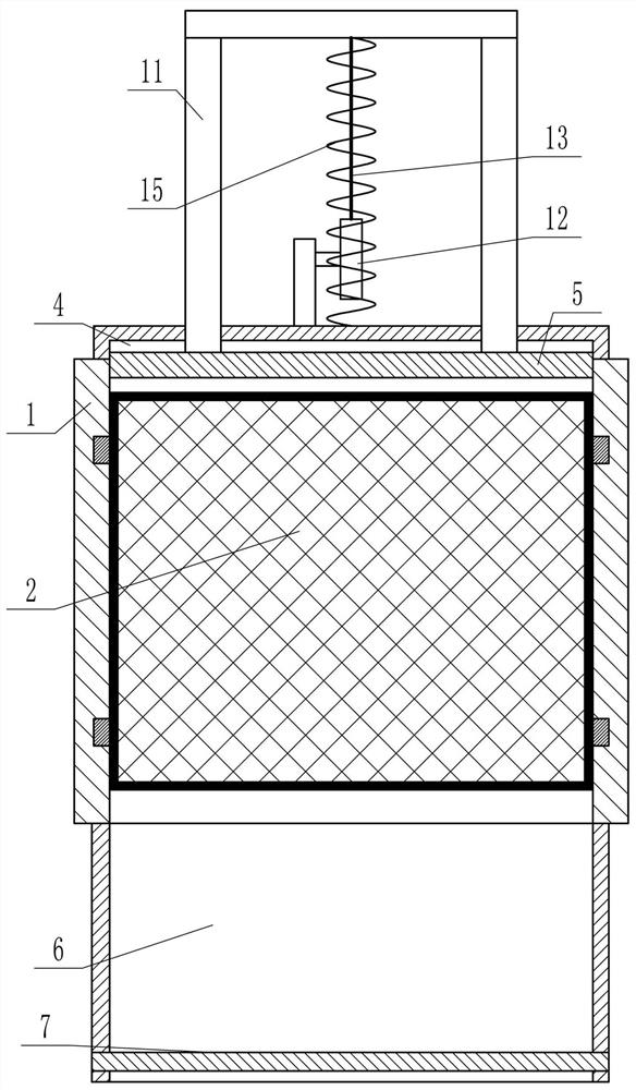
[0015] Depend on Figure 1 to Figure 2 It can be seen that the present invention comprises a square tube 1 placed horizontally in the left and right directions and open at both ends. A filter screen 2 that can slide left and right inside the square tube 1 and is as large as the vertical section of the inner chamber of the square tube 1 is installed in the square tube 1. The right side of 2 is provided with the first compression spring 3 that can make it reset to the left, and the inner wall of the square pipe 1 upper end is provided with a blind hole 4, and a blind hole 4 that can move up and down and can stretch out is installed in the blind hole 4. The scraper 5 of the square pipe 1 is provided with a collection box 6 corresponding to the blind hole 4, the upper end of the collection box 6 is open and communicated with...


PUM


Abstract

The invention relates to a hydraulic engineering filtering device, and aims to effectively solve the problem that impurities are hard to remove in a hydraulic water conveying process. According to thetechnical scheme, a square tube which is placed horizontally and bidirectionally, and is provided with openings at two ends is provided; a filter screen which can slide leftwards and rightwards inside the square tube and is equal to the vertical cross section of an inner cavity of the square tube in size is arranged in the square tube; the right side of the filter screen is provided with a firstpressure spring capable of resetting the filter screen leftwards; the inner wall of the upper end of the square tube is provided with a blind hole; a scraping board capable of moving upwards and downwards and extending out of the blind hole is arranged in the blind hole; a collection box corresponding to the blind hole is arranged below the square tube; the opening at the upper end of the collection box is communicated with the square tube; a movable door is arranged at the lower end of the collection box; a baffle plate of which the lower end side is attached to the bottom side of the squaretube is fixed to the right side of the filter screen; the baffle plate can move leftwards and rightwards along with the filter screen. The hydraulic engineering filtering device has the advantages ofnovel conception, skillful structure and high practicability.

Description

technical field [0001] The invention relates to the field of water conservancy engineering, in particular to a filter device for water conservancy engineering. Background technique [0002] In the construction of water conservancy projects, it is often necessary to transport water resources through pipelines, and there are often a large amount of dirt and impurities in the transported water. These dirt and impurities can easily cause blockage of pipelines and damage water conservancy equipment. , Therefore, it is necessary to set up a corresponding filter device to filter the dirt and impurities in the water. [0003] However, for the existing filtering devices, limited by the limitations in structure and design, they are often easily blocked by dirt and impurities, thereby greatly affecting the filtering effect. At the same time, the existing filtering devices are relatively difficult to maintain or repair It is troublesome, and the dirt and impurities therein are very inc...

Claims


Application Information

Patent Timeline
Patent Type & Authority Patents(China)
IPC IPC(8): B01D35/02B01D33/01
CPCB01D33/0158B01D35/02
Inventor 孙振友宋珍鹤介可及
Owner 福建艺景生态建设集团有限公司
Learn More