System for conveying objects from a nested stack of objects to a printer for printing
A technology of printing system and conveyor, which is applied in the field of printing on three-dimensional objects, and can solve problems such as difficulties
- Summary
- Abstract
- Description
- Claims
- Application Information
AI Technical Summary
Problems solved by technology
Method used
Image

Examples
Embodiment Construction
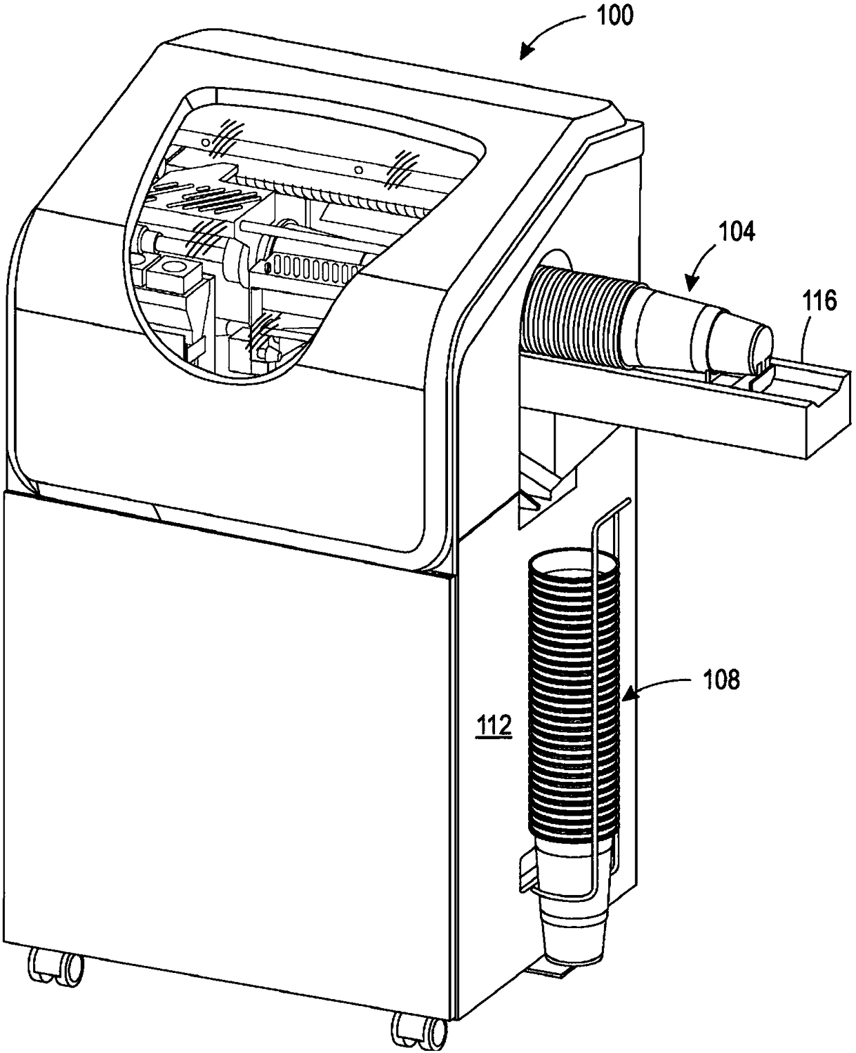
[0012] For a general understanding of embodiments of the invention, reference is made to the accompanying drawings. In the drawings, like reference numerals have been used to designate like elements throughout.
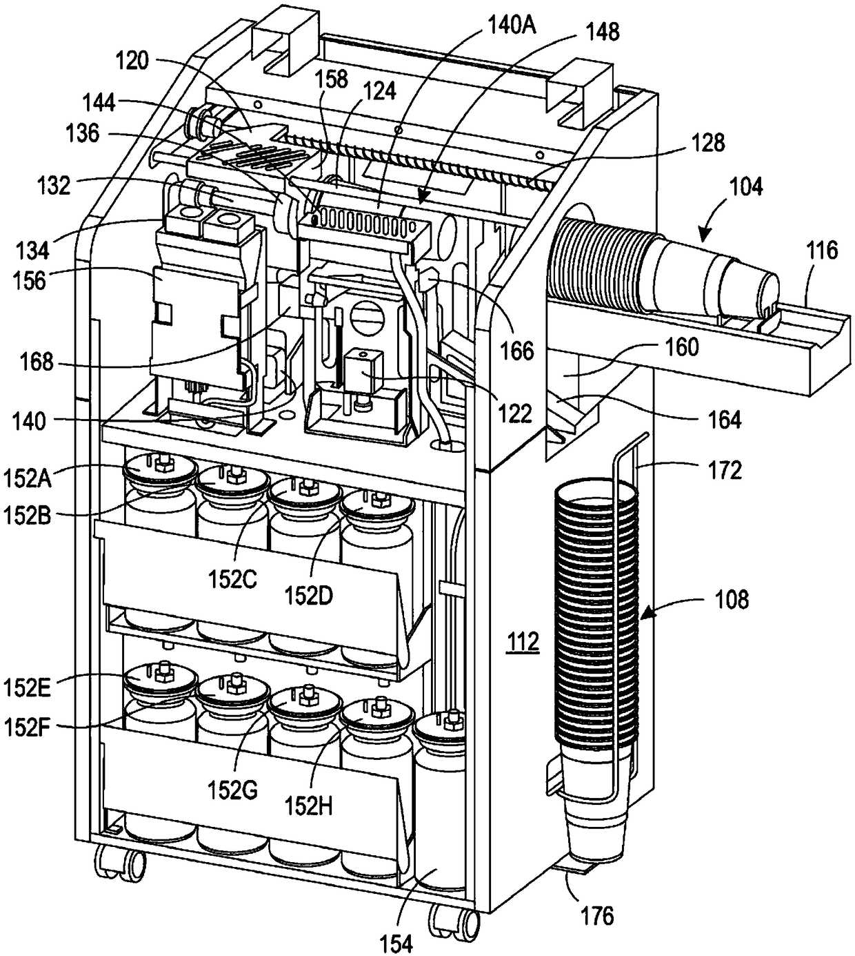
[0013] figure 1 A printing system 100 is depicted that is configured to retrieve an object from a stack 104 of nested objects, print a surface of the retrieved object, and eject the printed object into a nested stack 108 . Printing system 100 includes housing 112, such as figure 2 As shown in , the printer is positioned in the housing 112 for printing objects. As depicted in said figure, the nested stack of objects is a stack of plastic cups, but the nested stack can have any objects that can be nested together and exhibit a small hole at one end of the nested stack. Nested stack 104 is positioned within conveyor 116 for translation into enclosure 112 . Details of the conveyor structure are presented below.
[0014] exist figure 2 The internal components of pr...
PUM
 Abstract
Description
Claims
Application Information
 - R&D
- Intellectual Property
- Life Sciences
- Materials
- Tech Scout
- Unparalleled Data Quality
- Higher Quality Content
- 60% Fewer Hallucinations
Browse by: Latest US Patents, China's latest patents, Technical Efficacy Thesaurus, Application Domain, Technology Topic, Popular Technical Reports.
© 2025 PatSnap. All rights reserved.Legal|Privacy policy|Modern Slavery Act Transparency Statement|Sitemap|About US| Contact US: help@patsnap.com