Adjusting device of machine vision detecting system
What is Al technical title?
Al technical title is built by PatSnap Al team. It summarizes the technical point description of the patent document.
A technology of machine vision detection and adjustment device, applied in the direction of supporting machines, mechanical equipment, machines/brackets, etc., can solve problems such as large use limitations, difficult adjustment of detection positions and detection angles, and inability to guarantee the clarity of image capture.
Inactive Publication Date: 2018-11-23
中山市标致电子科技有限公司
View PDF0 Cites 8 Cited by
Summary
Abstract
Description
Claims
Application Information
AI Technical Summary
This helps you quickly interpret patents by identifying the three key elements:
Problems solved by technology
Method used
Benefits of technology
Problems solved by technology
[0002] The detection position and detection angle of the machine vision detection device in the prior art are not easy to adjust, the detection range is limited, and the use limitations are large; the machine vision detection device in the prior art has no focusing structure, and the clarity of picture acquisition cannot be guaranteed, so it is urgently needed An adjustment device for a machine vision inspection system to solve the above-mentioned problems
Method used
Image
Click on the blue label to locate the original text in one second.
Reading with bidirectional positioning of images and text.
Examples
Embodiment Construction
[0020] In order to make the technical means, creative features, goals and effects achieved by the present invention easy to understand, the present invention will be further described below in conjunction with specific embodiments.
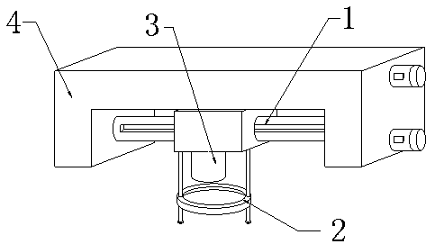
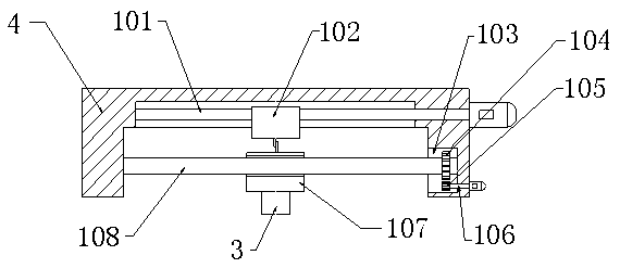
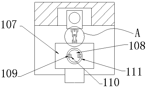
[0021] see Figure 1-Figure 5 , the present invention provides a technical solution: an adjustment device for a machine vision detection system, including a camera assembly 3, a bracket 4, an adjustment mechanism 1 and a zoom mechanism 2, the camera assembly 3 is arranged in the bracket 4, and the camera assembly 3 is adjusted by Mechanism 1 is connected with bracket 4, and adjustment mechanism 1 is arranged on the inner upper position of bracket 4, and adjustment mechanism 1 includes transverse screw rod 101, nut seat 102, cavity 103, driven gear 104, transmission gear 105, drive shaft 106, moving Seat 107, guide bar 108, limit block 109, limit draw-in groove 110, through hole 111, upper rotating seat 112, connecting rod one 113, connecting rod t...
PUM
Abstract
The invention provides an adjusting device of a machine vision detecting system. The adjusting device of the machine vision detecting system comprises a camera component, a bracket, an adjusting mechanism and a zooming mechanism. The camera component is installed in the bracket, and the camera component is connected with the bracket through the adjusting mechanism. The adjusting mechanism is installed at an upper position in the bracket. The adjusting mechanism comprises a transverse screw rod, a nut base, a cavity, a driven gear, a transmission gear, a driving shaft, a moving base, a guidingrod, a limiting locking block, a limiting locking groove, a through hole, an upper rotating base, a first connecting rod, a second connecting rod and a lower rotating base. The zooming mechanism is installed on the lower side face of the moving base. The zooming mechanism comprises a second bevel gear, a first bevel gear, a first belt pulley, a first screw, a frame, a convex lens, a second screw and a second belt pulley. Compared with the prior art, the adjusting device of the machine vision detecting system has the beneficial effect of realizing adjusting functions of a detecting position andan angle, and realizing a focal length adjusting function.
Description
technical field [0001] The invention relates to an adjustment device of a machine vision detection system, which belongs to the field of vision detection equipment. Background technique [0002] The detection position and detection angle of the machine vision detection device in the prior art are not easy to adjust, the detection range is limited, and the use limitations are large; the machine vision detection device in the prior art has no focusing structure, and the clarity of picture acquisition cannot be guaranteed, so it is urgently needed An adjustment device for a machine vision inspection system is provided to solve the above-mentioned problems. Contents of the invention [0003] In view of the deficiencies in the prior art, the purpose of the present invention is to provide an adjustment device for a machine vision inspection system to solve the problems raised in the background art above. [0004] In order to achieve the above object, the present invention is ac...
Claims
Application Information
Patent Timeline
Application Date:The date an application was filed.
Publication Date:The date a patent or application was officially published.
First Publication Date:The earliest publication date of a patent with the same application number.
Issue Date:Publication date of the patent grant document.
PCT Entry Date:The Entry date of PCT National Phase.
Estimated Expiry Date:The statutory expiry date of a patent right according to the Patent Law, and it is the longest term of protection that the patent right can achieve without the termination of the patent right due to other reasons(Term extension factor has been taken into account ).
Invalid Date:Actual expiry date is based on effective date or publication date of legal transaction data of invalid patent.