
Self-drawing-type electric heating shoe drying rack

A technology of electric heating and heating plate, applied in the cleaning of boots and shoes, filtration of dispersed particles, application, etc., can solve the problems of uncomfortable wearing, temperature loss, unpleasant odor, etc., and achieve the effect of avoiding the spread of odor

Active Publication Date: 2018-11-27
玉环昕旺科技有限公司
View PDF7 Cites 0 Cited by
  • Summary
  • Abstract
  • Description
  • Claims
  • Application Information

AI Technical Summary

Problems solved by technology

[0002] In order to keep warm, people wear cotton shoes in winter. Cotton shoes can provide better warmth for people's feet and avoid the rapid loss of the temperature of people's feet in cold winter. After a day, the humidity inside the cotton shoes is very high and needs to be dried, otherwise it will be very uncomfortable to wear the next day
[0003] Now it is more common at home to dry cotton shoes with a small sun, but cotton shoes will have an unpleasant smell under high temperature baking after wearing for a day, which will affect the indoor air environment, and the existing technology cannot solve this problem well, so There is an urgent need for a self-extracting electric heating shoe rack

Method used


Image

  • Self-drawing-type electric heating shoe drying rack
  • Self-drawing-type electric heating shoe drying rack
  • Self-drawing-type electric heating shoe drying rack

Examples


Embodiment Construction

[0024] The technical solutions in the embodiments of the present invention will be clearly and completely described below in conjunction with the embodiments of the present invention. Obviously, the described embodiments are only a part of the embodiments of the present invention, rather than all the embodiments. Based on the embodiments of the present invention, all other embodiments obtained by those of ordinary skill in the art without creative work shall fall within the protection scope of the present invention.

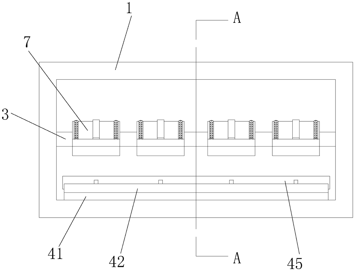
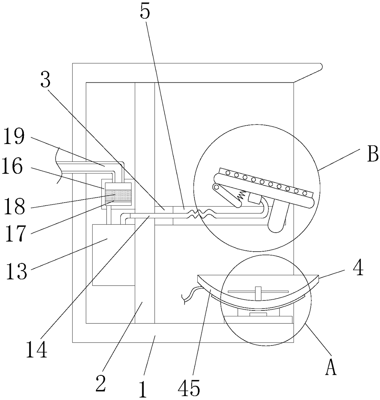
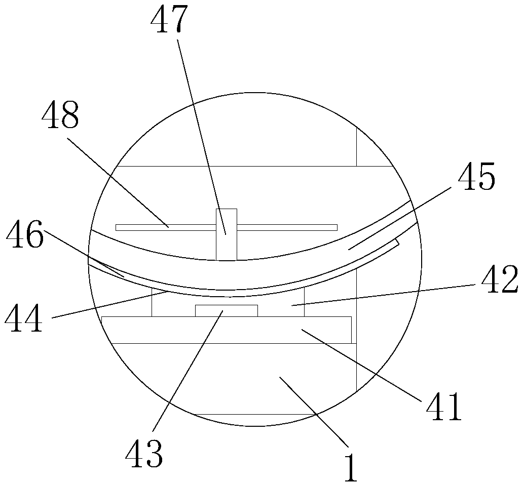
[0025] See Figure 1-6 , The present invention provides a technical solution: a self-extracting electric shoe drying rack, comprising a box body 1, a partition plate 2 is fixedly connected between the top wall and the bottom wall of the box body 1, and the left and right sides of the partition plate 2 are respectively It is fixedly connected with the left and right side walls inside the box 1, the middle of the front of the partition 2 is fixedly connected with the ...


PUM


Abstract

The invention belongs to the technical field of household electric appliances, and discloses a self-drawing-type electric heating shoe drying rack. The self-drawing-type electric heating shoe drying rack comprises a box body, partition plates are fixedly connected between the top and bottom walls of the box body, the left and right side faces of the partition plates are fixedly connected with theleft and right side walls in the box body respectively, and the middles of the front surfaces of the partition plates are fixedly connected with the back surface of a transverse plate; an electric heating device is arranged at the portion, located below the transverse plate, of the inner bottom wall of the box body, four notches are sequentially formed in the front surface of the transverse platefrom left to right, a support plate is fixedly connected to the ends, close to the front surface of the transverse plate and between the left and right side walls, in the notches, and the top of the support plate is fixedly connected with the front end of the lower surface of a placement plate. Through the arrangement of the support plate, the placement plate, isolation rods and a compression spring, the rack can be inserted in cotton shoes to have the support function; moreover, through the arrangement of the isolation rods, the contact between the placement plates and insoles can be reduced,and drying of the insole is prevented from being influenced; through the arrangement of the compression spring, a toe cap can be supported, and uniform drying of the cotton shoes is facilitated.

Description

Technical field [0001] The invention relates to the technical field of household appliances, in particular to a self-extracting electric heating shoe rack. Background technique [0002] In order to keep warm, people wear cotton shoes in winter. Cotton shoes can provide better warmth for people’s feet and prevent the temperature of people’s feet from quickly losing in the cold winter. However, cotton shoes are often worn by people because of their warmth. After a day, the humidity in the cotton shoes is very high and they need to be dried, otherwise they will be very uncomfortable to wear the next day. [0003] Nowadays, it is more common to use the sun to dry cotton shoes at home, but the cotton shoes will have an unpleasant smell under high temperature baking after wearing for a day, which will affect the indoor air environment. The existing technology cannot solve this well, so There is an urgent need for a self-extracting electric shoe drying rack. Summary of the invention [0...

Claims


Application Information

Patent Timeline
IPC IPC(8): A47L23/20
CPCA47L23/205B01D46/00B01D53/04B01D2257/90
Inventor 丁武轩
Owner 玉环昕旺科技有限公司
Learn More